Sheet forming of metallic glass by rapid capacitor discharge

Active Publication Date: 2012-10-11
CALIFORNIA INST OF TECH
View PDF10 Cites 23 Cited by
  • Summary
  • Abstract
  • Description
  • Claims
  • Application Information

AI Technical Summary

Benefits of technology

[0030]In still yet another embodiment, the tensile deformational force is controlled so that the flow of the material is Newtonian and failure by necking is avoided

Problems solved by technology

As such, conventional casting processes were not suitable for such high cooling rates, and special casting processes such as melt spinning and planar flow casting were developed.
Due to the crystallization kinetics of those early alloys being substantially fast, extremely short time (on the order of 10−3 seconds or less) for heat extraction from the molten alloy were required to bypass crystallization, and thus early amorphous alloys were also limited in size in at least one dimension.
Because the critical cooling rate requirements for these amorphous alloys severely limited the size of parts made from amorphous alloys, the use of early amorphous alloys as bulk objects and articles was limited.
However, even though bulk-solidifying amorphous alloys provide some remedy to the fundamental deficiencies of solidification casting, and particularly to the die-casting and permanent mold casting processes, as discussed above, there are still issues which need to be addressed.
For example, presently available BMGs with large critical casting dimensions capable of making large bulk amorphous objects are limited to a few groups of alloy compositions based on a very narrow selection of metals, including Zr-based alloys with additions of Ti, Ni, Cu, Al and Be and Pd-based alloys with additions of Ni, Cu, and P, which are not necessarily optimized from either an engineering or cost perspective.
In addition, the current processing technology requires a great deal of expensive machinery to ensure appropriate processing conditions are created.
These modified die-casting machines can cost several

Method used


Image

  • Sheet forming of metallic glass by rapid capacitor discharge
  • Sheet forming of metallic glass by rapid capacitor discharge
  • Sheet forming of metallic glass by rapid capacitor discharge

Examples


example 1

Study of Ohmic Heating

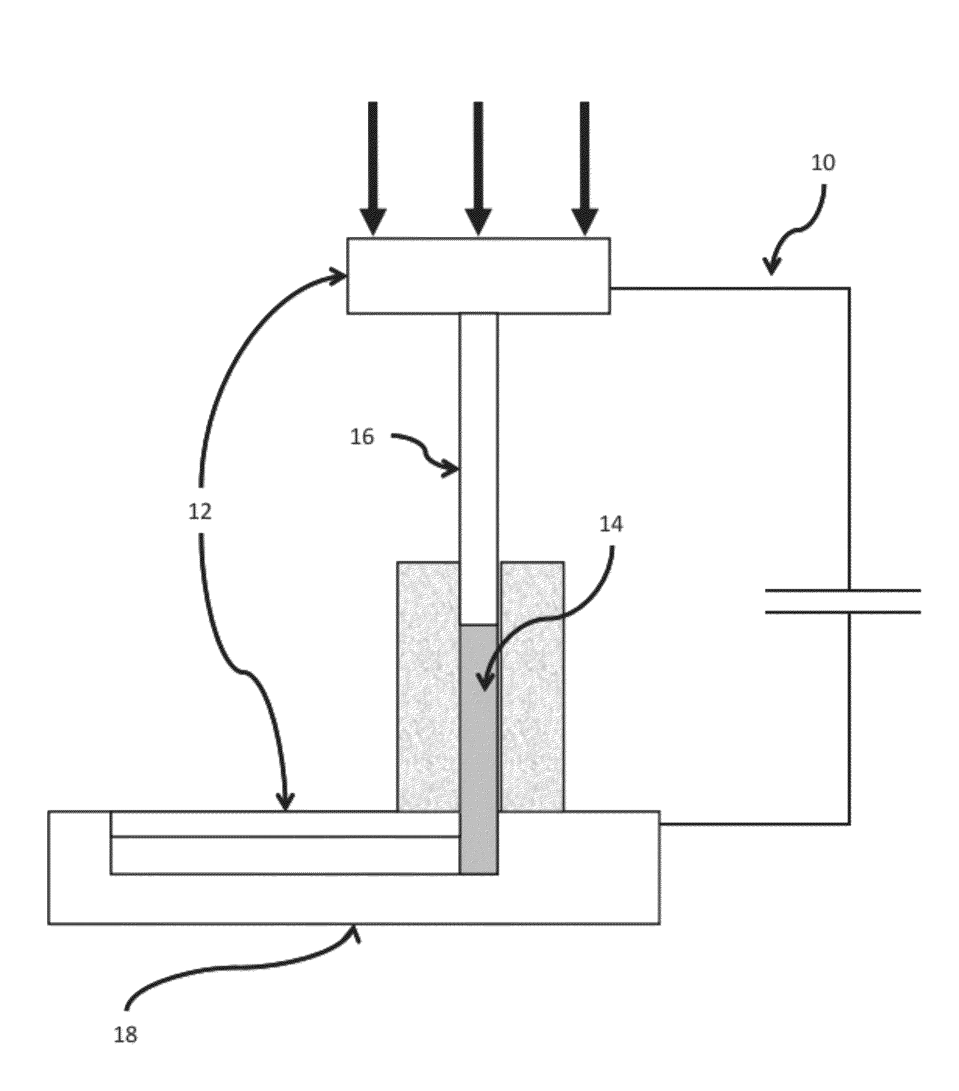
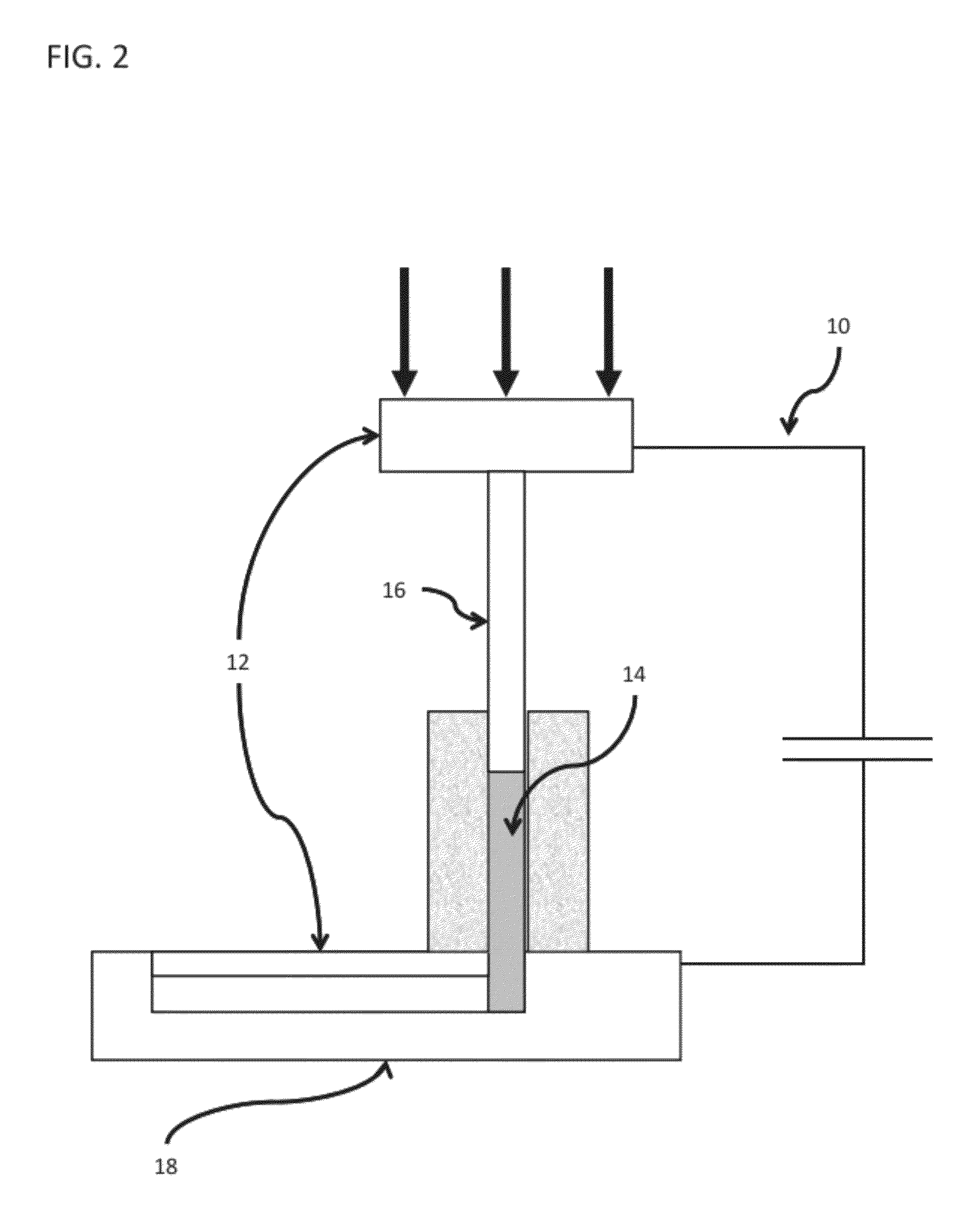
[0102]To demonstrate the basic principle that for BMGs capacitive discharge with Ohmic heat dissipation in a cylindrical sample will give uniform and rapid sample heating a simple laboratory spot welding machine was used as a demonstration shaping tool. The machine, a Unitek 1048 B spot welder, will store up to 100 Joules of energy in a capacitor of ˜10 μF. The stored energy can be accurately controlled. The RC time constant is of order 100 μs. To confine a sample cylinder, two paddle shaped electrodes were provided with flat parallel surfaces. The spot welding machine has a spring loaded upper electrode which permits application of an axial load of up to ˜80 Newtons of force to the upper electrode. This, in turn permits a constant compressive stress ranging to ˜20 MPa to be applied to the sample cylinder.

[0103]Small right circular cylinders of several BMG materials were fabricated with diameters of 1-2 mm and heights of 2-3 mm. The sample mass ranged from ˜40 ...

example 2

Injection Molding Apparatus

[0107]In another example, a working prototype RCDF injection molding apparatus was constructed. Schematics of the device are provided in FIGS. 11a to 11e. Experiments conducted with the shaping apparatus prove that it can be used to injection mold charges of several grams into net-shape articles in less than one second. The system as shown is capable of storing an electrical energy of ˜6 KJoules and applying a controlled process pressure of up to ˜100 MPa to be used to produce small net shape BMG parts.

[0108]The entire machine is comprised of several independent systems, including an electrical energy charge generation system, a controlled process pressure system, and a mold assembly. The electrical energy charge generation system comprises a capacitor bank, voltage control panel and voltage controller all interconnected to a mold assembly (60) via a set of electrical leads (62) and electrodes (64) such that an electrical discharge of may be applied to the...

example 3

Sheet Forming Apparatus

[0113]As described briefly above, the RCDF method of the current invention may be used to form metallic glass sheets. Sheet forming of polymeric materials, a process called “calendering”, involves softening of the polymer to reach viscosities in the range of 100 to 10000 Pa-s, and subsequently force the melt through a pair (or a series of pairs) of rotating rollers (twin rollers) in a manner that the melt is formed into a sheet shape and is simultaneously cooled and re-vitrified. The calendering process relies on the ability of polymeric materials to attain, by conventional heating, undercooled liquid states that are characterized by viscosities in the range of 100 to 10000 Pa-s without crystallizing on the time scale of the calendaring process. Metallic glasses, on the other hand, are not able to attain undercooled liquid states of such viscosity range by conventional heating, because those states in a metallic glass are highly unstable against crystallizatio...


PUM

PropertyMeasurementUnit
Temperatureaaaaaaaaaa
Timeaaaaaaaaaa
Timeaaaaaaaaaa

Abstract

An apparatus and method of uniformly heating, rheologically softening, and thermoplastically forming metallic glasses rapidly into a net shape using a rapid capacitor discharge forming (RCDF) tool are provided. The RCDF method utilizes the discharge of electrical energy stored in a capacitor to uniformly and rapidly heat a sample or charge of metallic glass alloy to a predetermined “process temperature” between the glass transition temperature of the amorphous material and the equilibrium melting point of the alloy in a time scale of several milliseconds or less. Once the sample is uniformly heated such that the entire sample block has a sufficiently low process viscosity it may be shaped into high quality amorphous bulk articles via any number of techniques including, for example, injection molding, dynamic forging, stamp forging, sheet forming, and blow molding in a time frame of less than 1 second.

Description

CROSS-REFERENCE TO RELATED APPLICATIONS[0001]This application is a continuation-in-part of U.S. application Ser. No. 12 / 409,253, filed Mar. 23, 2009, and claims priority to U.S. Provisional Application No. 61 / 070,284, filed Mar. 21, 2008. This application also claims priority to U.S. Provisional Application 61 / 426,685, filed Dec. 23, 2010, the disclosures of which are incorporated herein by reference.FIELD OF THE INVENTION[0002]This invention relates generally to a novel method of forming metallic glass; and more particularly to a process for forming metallic glass using rapid capacitor discharge heating.BACKGROUND OF THE INVENTION[0003]Amorphous materials are a new class of engineering material, which have a unique combination of high strength, elasticity, corrosion resistance and processability from the molten state. Amorphous materials differ from conventional crystalline alloys in that their atomic structure lacks the typical long-range ordered patterns of the atomic structure o...

Claims


Application Information

Patent Timeline
IPC IPC(8): B21D37/16
CPCB21C37/02B21J1/006C21D1/34C21D1/38C21D1/40C21D7/13B21C29/003C22C1/002C22C45/00C22C45/003C22F1/00B21B15/00C21D2201/03C22C1/11C21D11/00B21B3/00B21B27/08B21B2027/086
Inventor JOHNSON, WILLIAM L.DEMETRIOU, MARIOS D.SCHRAMM, JOSEPH P.
Owner CALIFORNIA INST OF TECH
Why Eureka
Try Eureka