
Laser desorption ionization mass spectrometry using a particulate separation bed

a technology of mass spectrometry and particulate separation, which is applied in the direction of particle separator tube details, dispersed particle separation, separation processes, etc., can solve the problems of reducing separation resolution, reducing mass accuracies, and limited dynamic range, so as to improve the effectiveness of separating analytes and efficiently absorb laser energy

Active Publication Date: 2015-10-01
PURDUE RES FOUND INC +1
View PDF7 Cites 20 Cited by
  • Summary
  • Abstract
  • Description
  • Claims
  • Application Information

AI Technical Summary

Benefits of technology

This patent discusses the use of a colloidal crystal called silica that can be enhanced with additives to improve its ability to separate analytes, act as a MALDI target, or both. The silica colloidal crystal can be coated with a substance that binds with the analyte and immobilizes it when exposed to a laser beam. The coating can also be made acidic to aid in ionization or include cinnamic acid to efficiently absorb laser energy. Overall, this patent provides a method for improving the accuracy and efficiency of separating and analyzing substances using a silica colloidal crystal.

Problems solved by technology

Certain CE-based methods have enabled automation and accurate, repeatable quantification, but exhibit limited dynamic range and require a number of complex, time-consuming steps (see, e.g., O'Neill, et al.
Certain microfluidic-based methods have increased binding efficiency and reduced complexity, but these methods are also characterized by reduced separation resolution (see, e.g., Hughes, et al.
The matrix, however, also generates adducts (i.e., chemical addition product-caused artifacts) that can mask results, reduce mass accuracies, and preclude the analysis of analytes with low molecular weights.
Co-crystallization of matrix and sample can also be problematic as heterogeneous co-crystallization or variations in crystal sizes can result in poor shot-to-shot reproducibility and reduced mass accuracy.
The use of MALDI-MS in the field of glycomics, for example, is often hindered by poorly resolved peaks among differentially modified proteins, limitations in the ability to analyze small carbohydrates, and the appearance of matrix adducts that can mask results.

Method used


Image

  • Laser desorption ionization mass spectrometry using a particulate separation bed
  • Laser desorption ionization mass spectrometry using a particulate separation bed
  • Laser desorption ionization mass spectrometry using a particulate separation bed

Examples


example 1

One-Dimensional Separation and MALDI-TOF MS Analysis of a Protein Mixture

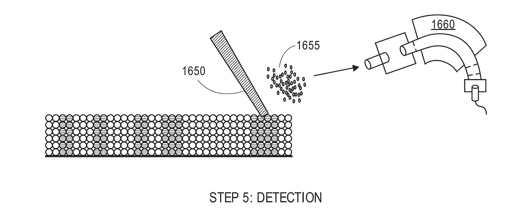
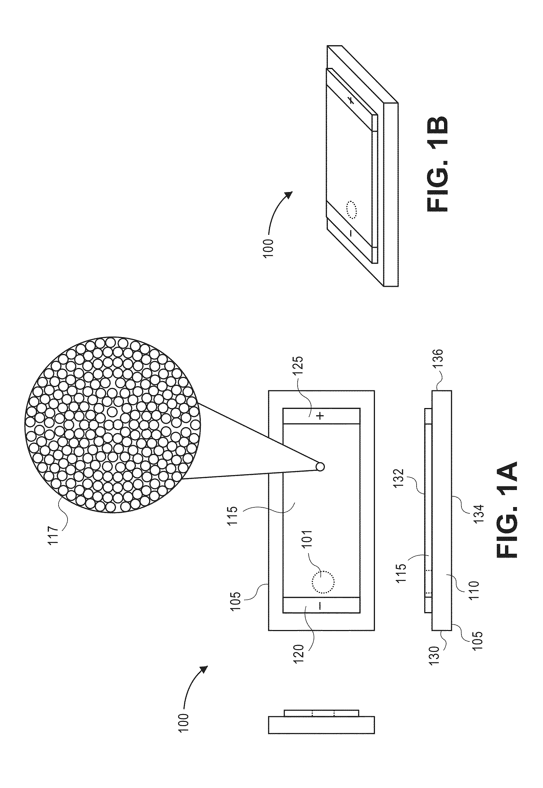
[0165]A glass slide is chemically modified with a solution of n-butyldimethylchlorosilane in anhydrous toluene under nitrogen. The slide is then rinsed with dry toluene and dried under vacuum at 80° C. A 1-mm-wide stripe of 1 cm in length is masked off on the slide and chemically etched with an ammonium bifluoride salt paste. A second, chemically-modified glass slide is used to cover the separation bed, and the assembly is secured using binder clips. A 10% w / w silica colloid is wicked into the separation bed and allowed to dry at room temperature. After drying, the cover glass slide is removed and the packed separation bed is silylated with a polymerization initiator. Linear polyacrylamide chains are grown using a complex of CuCl with tris(2-dimethylaminoethyl) amine as the catalyst; the slide is immersed in a solution of acrylamide monomer and CuCl catalyst, and the mixture is allowed to polymerize.

[0166]The s...

example 2

Two-Dimensional Separation and MALDI-TOF MS Analysis of a Protein Mixture

[0169]A pH gradient is established across a separation bed packed with silica particles (fabricated as described above) using a commercially available carrier ampholyte mixture.

[0170]Proteins (myoglobin from equine skeletal muscle, cytochrome c from bovine heart and lysozyme from chicken egg white) are dissolved in PBS and combined in an isoelectric focusing solution (8 M urea; 20 mM DTT; 0.5% Triton X-100). The concentration of each protein is about 0.05 mg / mL.

[0171]Proteins are electrokinetically loaded into the prepared separation bed under 300 V / cm for 30 s. Isoelectric focusing is conducted by ramping the voltage from 50 V / cm to 1000 V / cm over a period of time sufficient for separation of the proteins.

[0172]The separation bed is aligned with a second separation bed equilibrated with SDS running buffer (25 mM Tris; 192 mM glycine; 0.1% (w / v) SDS; pH 8.0). A voltage of 50 V / cm is applied across the aligned s...

example 3

Two-Dimensional Separation and MALDI-TOF MS Analysis of a Protein Mixture

[0174]A separation bed packed with silica particles is fabricated as described above, and a first region of the surface (i.e., a first dimension) is isolated from the rest of the crystal (i.e., a second dimension) by creating a physical gap between the two crystal areas or by using a manifold to separate the areas. A pH gradient is established across the isolated region using a commercially available carrier ampholyte mixture.

[0175]Proteins (myoglobin from equine skeletal muscle, cytochrome c from bovine heart and lysozyme from chicken egg white) are dissolved in PBS and combined in an isoelectric focusing solution (8 M urea; 20 mM DTT; 0.5% Triton X-100). The concentration of each protein is about 0.05 mg / mL.

[0176]The proteins are loaded into the first region of the surface, and isoelectric focusing is conducted by ramping the voltage from 50 V / cm to 1000 V / cm over a period of time sufficient for separation of...


PUM


Abstract

A self-assembled engineered lattice of nanometer-scale silica particles, or other suitable particles generally resembling regularly-sized spheres, is configured in a separation bed for electrophoresis, isoelectric focusing, chromatography, or other voltage-induced separation of analytes. After separation, the analytes are immobilized on the separation bed and then ionized using matrix-assisted laser desorption / ionization (MALDI) for use with a mass spectrometer. The nanoparticles can be coated with polymers that activate to immobilize the analytes or assist with MALDI. The separation can occur in two dimensions.

Description

CROSS-REFERENCES TO RELATED APPLICATIONS[0001]This application claims the benefit of U.S. Provisional Application No. 61 / 970,857, filed Mar. 26, 2014 and U.S. Provisional Application No. 61 / 970,818, filed Mar. 26, 2014, the disclosures of which are incorporated by reference in their entireties for all purposes.STATEMENT AS TO RIGHTS TO INVENTIONS MADE UNDER FEDERALLY SPONSORED RESEARCH AND DEVELOPMENT[0002]This invention was made with government support under CA161772 and GM112387 awarded by the National Institutes of Health. The government has certain rights in the invention.COPYRIGHT NOTICE[0003]A portion of the disclosure of this patent document contains material which is subject to copyright protection. The copyright owner has no objection to the facsimile reproduction by anyone of the patent document or the patent disclosure, as it appears in the Patent and Trademark Office patent file or records, but otherwise reserves all copyright rights whatsoever.BACKGROUND[0004]1. Field o...

Claims


Application Information

Patent Timeline
IPC IPC(8): H01J49/16H01J49/00
CPCH01J49/0027H01J49/164H01J49/0418
Inventor FURTAW, MICHAEL D.ANDERSON, JON P.WIRTH, MARY J.BIRDSALL, ROBERT E.HUA, YIMINZHANG, ZHAORUI
Owner PURDUE RES FOUND INC
Learn More