Portable Apparatus for Soil Chemical Characterization

a portable, soil technology, applied in the chemical field, can solve the problems of laborious and costly laboratory methods for soil salinity characterization, limited methods, and large number of soil samples, and achieve the effect of optimal soil salinity prediction, convenient and fast collection, and convenient collection

Active Publication Date: 2017-05-04
TEXAS TECH UNIV SYST +1
View PDF4 Cites 54 Cited by
  • Summary
  • Abstract
  • Description
  • Claims
  • Application Information

AI Technical Summary

Benefits of technology

[0018]Three alternative methods (VisNIR DRS, PXRF, and RS) for determining soil characteristics were compared to traditional laboratory analysis. With respect to soil salinity, elemental concentrations (determined via PXRF) of S and Cl were found to be most strongly correlated to soil EC (1:5). With consideration of VisNIR DRS data, two multivariate algorithms were tested (PLS and SVR) and generally produced strong, significant relationships to soil EC (1:5). Comparing the relative accuracies of PXRF and RS in predicting soil EC (1:5), both produced suboptimal results relative to VisNIR DRS alone. Evaluated independently, the techniques were generally ranked as VisNIR DRS>PXRF>RS. Conversely, the synthesis of VisNIR DRS and PXRF datasets produced predictive results better than the prior art. The synthesis of all three datasets produced the best predictive results; better than any one technique taken independently. As these types of data are quick, easy, and inexpensive to collect, two or three datasets can be combined for optimal soil salinity prediction. The present invention provides researchers with a tool that obtains results of comparable quality to lab-derived data, yet with less time and effort than traditional laboratory salinity determinations.

Problems solved by technology

Yet, traditional laboratory methods for soil salinity characterization can be laborious and costly.
Thus, a large number of soil samples are often required to adequately characterize soil salinity across landscapes.
While promising, these methods are limited by factors such as spatial and spectral resolution of the image, vegetation coverage, and atmospheric effects ([16]; Metternich and Zinck, 2008).
Thus, the number of such studies featuring quantitative assessment of soil salinity under natural field conditions is limited.
Soil TC loss due to cultivation degrades soil fertility and quality, reduces biomass productivity, and adversely impacts water quality; depletions exacerbated by projected global warming [79, 86].
However, excessive nitrogen contents in soil not only lead to non-point source pollution, such as eutrophication and associated water-quality problems [61, 124], but also can be released to the atmosphere as greenhouse gases (e.g., nitrous oxide, N2O) [81].
Dry combustion requires separate determinations for inorganic- and organic-C, is time consuming, relatively expensive, and not adaptable to in situ determinations [99].
Wet combustion is a semi-quantitative estimate of soil carbon due to the lack of a universal conversion factor for each soil analyzed; it is time-consuming, tedious, and generates toxic waste that must be disposed of properly [92, 66].
Another relatively inexpensive and rapid technique, loss-on-ignition (LOI) has been shown to be inaccurate in some instances due to the decomposition of certain mineral fractions at high temperatures [92, 79].
However, both methods are time consuming, destructive to the sample being analyzed, and fail to recover some forms of N, particularly N in certain heterocyclic compounds and compounds containing N—N and N—O linkages [54].
The Dumas method is also expensive and has lower precision than Kjeldahl approaches [54].
However, interference from other similar and undesired ions can be problematic; sometimes causing instability in attaining equilibrium [78].
Also, cell membranes, reference electrodes, and amplifier distortions may cause anomalous readings [78].
The disadvantages of all these traditional laboratory analysis methods are compounded by the large number of samples required for accurate assessment [84, 86].
Although these traditional methods are relatively accurate and widely accepted, they require extensive lab work and destroy the sample during processing.
Although these studies obtained excellent results, which showed that it is a viable alternative for the routine quantitative analysis of soil carbon, lab-based VisNIR can only provide semi-quantitative estimation with residual prediction deviation (RPD)=1.5-2.0 [57].
[89] found VisNIR spectra alone do not provide sufficient accuracy for stand-alone C sequestration measurement, monitoring and verification.
VisNIR spectroscopy alone will never provide complete soil characterization.
However, PXRF cannot presently be used to quantify lighter elements [94] (e.g., Na, N, C, H, Li) given their stable electron configurations and low fluorescent energies.
Few studies have attempted to predict soil carbon and nitrogen by using PXRF, given that indirect approaches to these determinations are required as direct measurements are not possible.
However, single sensors provide no robust capability to measure soil properties successfully at different sampling sites because of the complex nature of soils [117].
The growth of the petroleum industry worldwide and marketing of petroleum products have resulted in countless chances for spillage.
Most commonly, when an underground storage tank is removed, soil petroleum contamination is discovered which may pose an even more worrisome problem, groundwater contamination.
Moreover, environmental pollution resulting from crude oil drilling has put numerous food crops under considerable risk [160].
To date, the total costs associated with lost jobs, contaminated food and water, cleanup, restoration, and environmental damage have not been fully determined [133] and may not be for many years.
Rapid and wide scale characterization of soil petroleum contamination is not feasible with traditional gas chromatography based methods since these are prohibitively expensive, extremely laborious, time consuming, sometimes show high variability (an order of magnitude) in TPH results across commercial laboratories, lack field-portability, and warrant rigorous field sampling [140, 153].

Method used


Image

  • Portable Apparatus for Soil Chemical Characterization
  • Portable Apparatus for Soil Chemical Characterization
  • Portable Apparatus for Soil Chemical Characterization

Examples


Embodiment Construction

[0050]While the making and using of various embodiments of the present invention are discussed in detail below, it should be appreciated that the present invention provides many applicable inventive concepts that can be embodied in a wide variety of specific contexts. The specific embodiments discussed herein are merely illustrative of specific ways to make and use the invention and do not delimit the scope of the invention.

[0051]To facilitate the understanding of this invention, a number of terms are defined below. Terms defined herein have meanings as commonly understood by a person of ordinary skill in the areas relevant to the present invention. Note that these terms may be used interchangeable without limiting the scope of the present invention. Terms such as “a”, “an” and “the” are not intended to refer to only a singular entity, but include the general class of which a specific example may be used for illustration. The terminology herein is used to describe specific embodimen...


PUM

PropertyMeasurementUnit
electrical conductivityaaaaaaaaaa
temperatureaaaaaaaaaa
areaaaaaaaaaaa

Abstract

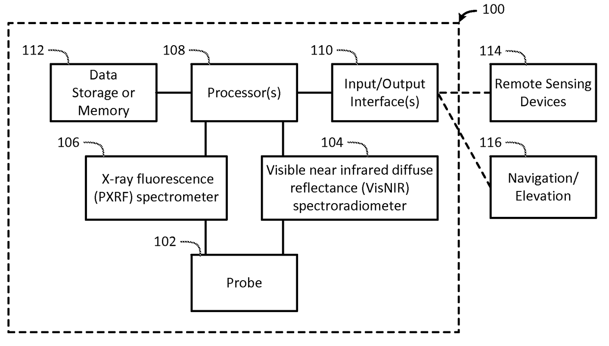
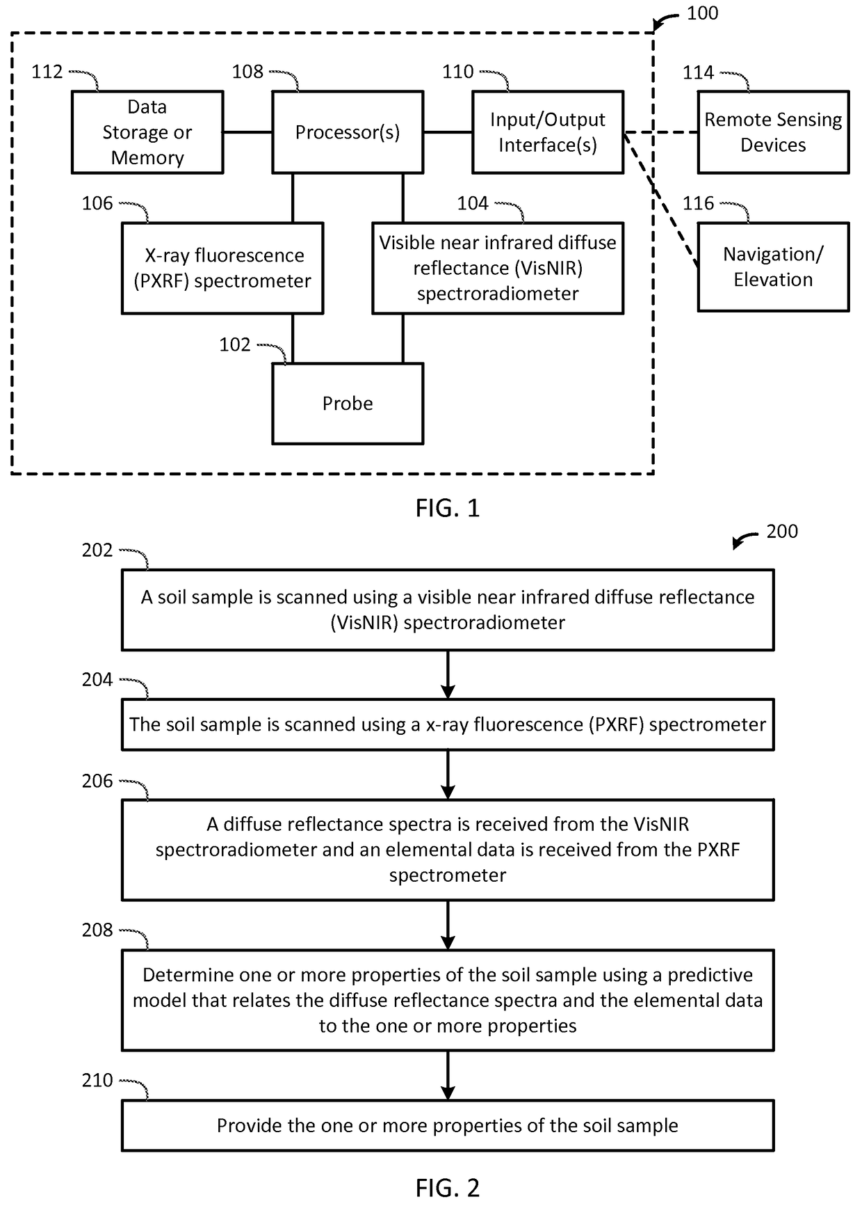
The present invention determines one or more properties of a soil sample by scanning a soil sample using a visible near infrared diffuse reflectance diffuse reflectance (VisNIR) spectroradiometer, scanning the soil sample using a x-ray fluorescence (PXRF) spectrometer, receiving a diffuse reflectance spectra from the VisNIR spectroradiometer and an elemental data from the PXRF spectrometer, determining one or more properties of the soil sample using one or more processors and a predictive model that relates the diffuse reflectance spectra and the elemental data to the one or more properties, and providing the one or more properties of the soil sample to one or more input/output interface.

Description

FIELD OF INVENTION[0001]The present invention relates generally to the field of chemical and, more particularly, to a portable apparatus for soil chemical characterization using x-ray fluorescence spectrometry and visible near infrared diffuse reflectance spectroscopy.BACKGROUND ART[0002]Soil Salinity:[0003]Salt affected soils are caused by excess accumulation of salt typically most pronounced at the soil surface. Salt is often derived from geological formations featuring shale, marl, limestone, sylvite, gypsum, and halite. Variability of soil salinity is affected by parent material, soil type, and landscape position [10]. Moreover, salts can be transported to the soil surface by capillary action from brackish water tables and accumulated due to evaporation. They can also accumulate as a result of anthropogenic activities such as fertilization or oil production. Soil salinity is generally measured via electrical conductivity (EC) in soil saturated paste (ECp), its liquid extract (EC...

Claims


Application Information

Patent Timeline
Patent Type & Authority Applications(United States)
IPC IPC(8): G01N23/22G01N33/24G01N21/3563G01N21/359G01N23/223
CPCG01N23/2206G01N21/359G01N23/223G01N21/3563G01N2223/33G01N2223/071G01N2223/616G01N2201/12G01N2201/10G01N33/24
Inventor WEINDORF, DAVIDCHAKRABORTY, SOMSUBHRA
Owner TEXAS TECH UNIV SYST
Why Eureka
Try Eureka