Improved Method and System of Carbon Sequestration and Carbon Negative Power System

Active Publication Date: 2020-08-27
ENHANCED ENERGY GRP
View PDF0 Cites 5 Cited by
  • Summary
  • Abstract
  • Description
  • Claims
  • Application Information

AI Technical Summary

Benefits of technology

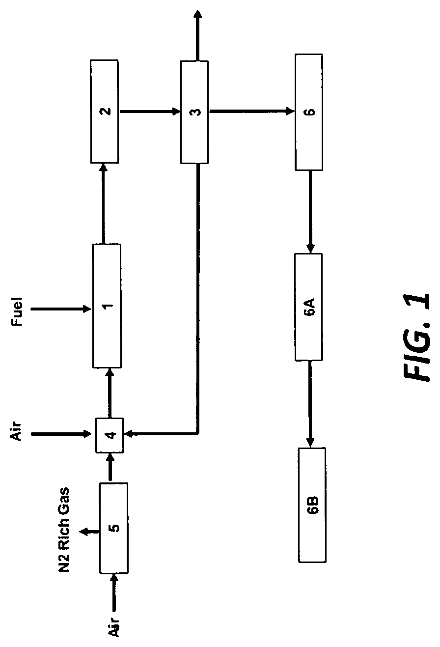
The invention is a system and method for sequestering carbon in a pyrolysis system. The system is compact, operates at high exhaust pressures, and integrates engine operation, heat recovery, and carbon capture. The system is capable of using both the oil and fuel from the pyrolysis process, reducing carbon dioxide emissions. The system also captures carbon from the engine exhaust and the pyrolysis exhaust, and operates in a way that does not require major engine modifications. The combination of these attributes results in a highly carbon-negative power system. The system includes a pyrolysis unit with a burner designed to consume excess oxygen from the engine exhaust and a burner designed to use liquid pyrolysis products. The system also includes an exhaust that is combined with the engine exhaust, enabling carbon capture and lower temperature operation. The pyrolysis oil produced can be used in the dual fuel engine.

Problems solved by technology

Emissions of the untreated flue gas to the air, while simple to execute, is not desirable for environmental reasons.
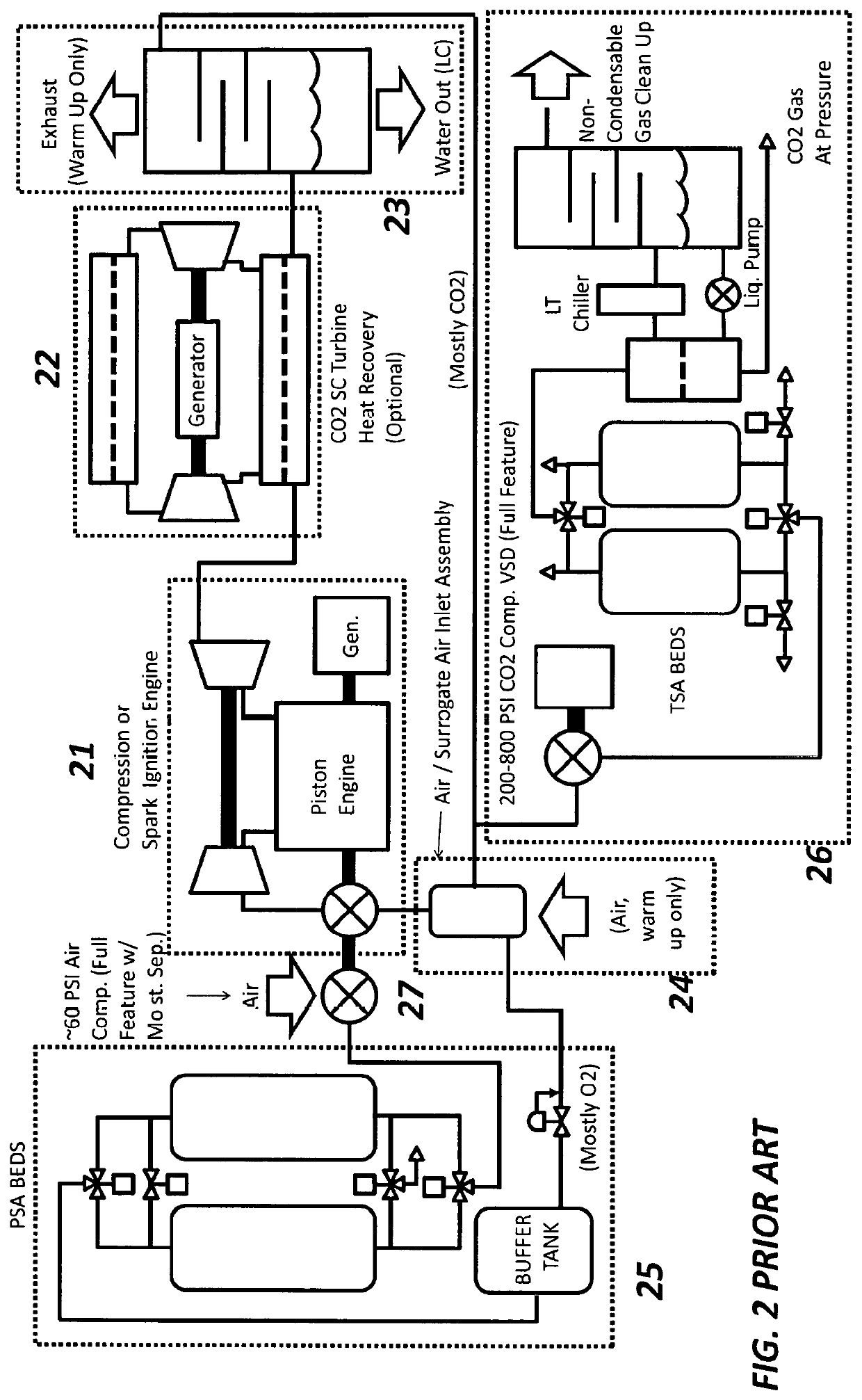
In special purpose applications, in particular for undersea applications, the requirement to tie the system exhaust pressure to the ambient pressure (elevated backpressure) can lower engine cycle efficiency significantly.
In other special purpose applications, in particular at higher altitudes, the requirement to tie the system pressure to the ambient pressure (reduced inlet pressure) can reduce specific power significantly, and may also impact efficiency.
Nevertheless, many of these engines have exhaust which is released to the atmosphere, and these “renewable fuels” create exhausts that are actually quite high in CO2.
Landfill gas is probably the worst, since it is about 50% CO2 to start with, it physically results in +3,000 lb.
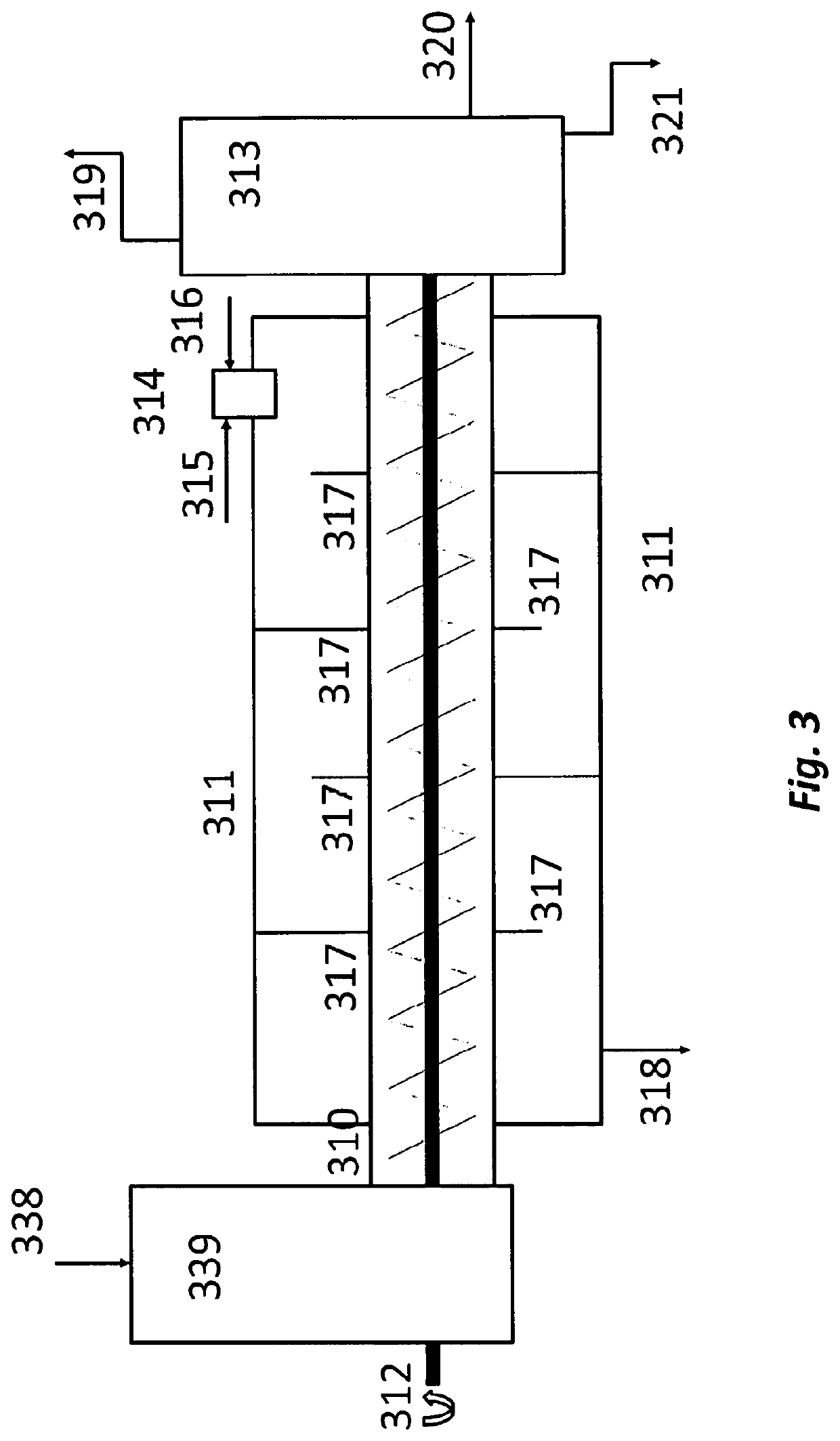
These issues, include, but are not limited to: high cost of pyrolysis equipment due to exotic alloys used in construction; high portion of high value (gaseous) fuel that the pyrolysis system produces that must be used to sustain the required temperatures; lack of value from pyrolysis oil / tar generated from certain feedstocks; and emissions, to include CO2 emissions and other regulated pollutants, from the burners used to sustain the required temperatures in pyrolysis reactors.
Those issues, include, but are not limited to: operation with levels of exhaust gas recirculation (EGR) that are too high can lead to creation of carbonic acid, as a result of CO2 dissolving in any liquid water that might occur in the SCC; operation with high levels of EGR also typically requires a high purity oxygen source to compensate for the inert components, leading to higher oxygen cost and exotic oxygen plants; high EGR levels, when combined with higher purity oxygen mixtures, result in a working fluid which is radically different than air in terms of both density (due to molecular weight and other factors) and specific heat ratio; a working fluid radically different from air will in general require significant engine modifications in a piston engine (for example: compression ratio, valve timing) and in the case of a gas turbine new turbo machinery designed specifically for the SCC working fluid (for example: the high pressure supercritical CO2 turbines vs. air breathing conventional gas turbines); unless oxygen is wasted, the SCC will tend to have a lower exhaust O2 level than “design point” in excess air machines, to include lean burn piston engines and gas turbines; and if exhaust O2 levels are allowed to drop, to compensate for the additional working fluid brought back into the cycle via EGR, and to save on O2 plant costs, then at some point those levels will be too low to sustain combustion at all (O2 limit for flammability in methane is around 12%) and in nearly all cases modification to the engine control system and in the gas of the gas turbine combustion is required.

Method used


Image

  • Improved Method and System of Carbon Sequestration and Carbon Negative Power System
  • Improved Method and System of Carbon Sequestration and Carbon Negative Power System
  • Improved Method and System of Carbon Sequestration and Carbon Negative Power System

Examples


Embodiment Construction

[0052]The present invention is now described more fully with reference to the accompanying drawings, in which an illustrated embodiment of the present invention is shown. The present invention is not limited in any way to the illustrated embodiment as the illustrated embodiment described below is merely exemplary of the invention, which can be embodied in various forms, as appreciated by one skilled in the art. Therefore, it is to be understood that any structural and functional details disclosed herein are not to be interpreted as limiting, but merely as a basis for the claims and as a representative for teaching one skilled in the art to variously employ the present invention. Furthermore, the terms and phrases used herein are not intended to be limiting but rather to provide an understandable description of the invention.

[0053]Where a range of values is provided, it is understood that each intervening value, to the tenth of the unit of the lower limit unless the context clearly d...


PUM


Abstract

An improved method and system of carbon sequestration of a pyrolysis piston engine power system is provided. The system includes a pyrolysis piston engine for generating power and exhaust gas and a water cooling and separation unit which receives the exhaust gas and cools and removes water from the exhaust gas to create C02 gas supply. The system also includes a mixing pressure vessel which receives at least a portion of the C02 gas supply from the water cooling and separation unit and mixes the C02 gas supply with oxygen to create a working fluid to be provided to the piston engine and an oxygen generator for providing oxygen to the mixing pressure vessel. The system also includes a pyrolysis interface for inputting byproducts from a pyrolysis system, wherein the pyrolysis interface comprises a pyrolysis gas interface and a pyrolysis gas / oil interface.

Description

CROSS-REFERENCE TO RELATED APPLICATIONS[0001]The present application is related to, claims the earliest available effective filing date(s) from (e.g., claims earliest available priority dates for other than provisional patent applications; claims benefits under 35 USC § 119(e) for provisional patent applications), and incorporates by reference in its entirety all subject matter of the following listed application(s) (the “Related Applications”) to the extent such subject matter is not inconsistent herewith; the present application also claims the earliest available effective filing date(s) from, and also incorporates by reference in its entirety all subject matter of any and all parent, grandparent, great-grandparent, etc. applications of the Related Application(s) to the extent such subject matter is not inconsistent herewith:[0002]U.S. provisional patent application 62 / 545,497 entitled “Improved Method of Carbon Sequestration”, naming Paul M. Dunn as inventor, filed 15 Aug. 2017.B...

Claims


Application Information

Patent Timeline
IPC IPC(8): F02B47/10F01K23/10F01K23/06
CPCF01K23/10F01K23/065F02B47/10F01N5/02F02G5/02F02G2250/03F01N2240/02F01N3/005F01N2570/10C01B13/0248C01B13/0251C01B13/0259C01B13/0277Y02E20/18F01K25/103F01K7/32F01K23/067F02M26/36F02M26/35
Inventor DUNN, PAUL M
Owner ENHANCED ENERGY GRP
Why Eureka
Try Eureka