

Carbon dioxide separation membranes and process
a carbon dioxide and separation membrane technology, applied in the field of thin film composite membranes and processes, can solve the problems of low selectivity of membrane materials with high permeability, economic challenges in separation, and vice versa, and achieve the effect of facilitating the high co2 permean
- Summary
- Abstract
- Description
- Claims
- Application Information
AI Technical Summary
Benefits of technology
Problems solved by technology
Method used
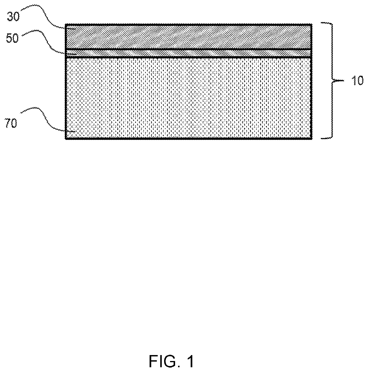
Image

Examples
example 1
[0035]Synthesis and Hydrolysis of PDD / VF / PPSF (Feed Ratio: 1 / 2 / 1.5) Terpolymer:
[0036]Into a 150-mL stainless steel pressure vessel, after argon purging for 5 minutes, were added a magnetic stirring bar, 10.5-g PPSF, 6.1-g PDD, 32-mL Vertrel®XF, 0.6-mL and HFPO dimer peroxide (0.15 M) in Vertrel®XF. The pressure vessel was sealed, initially cooled to 0° C. then charged with 2.3-g of vinyl fluoride gas. The reaction mixture was stirred at room temperature in a water bath overnight. The reaction vessel was brought to ambient atmospheric pressure, opened, and 50 mL of methanol was added to the reaction mixture. The precipitated gel was transferred to a glass dish and dried in a fume hood at ambient temperature to remove the majority of volatile components, and then in a forced air oven at 80° C. for 6 hours to yield 10.7 g of PDD / VF / PPSF terpolymer as a pale color solid. Glass transition temperature (Tg)=55° C.
[0037]10.7-g of PDD / VF / PPSF terpolymer synthesized in the above procedure, 20...
example 2
[0038]Membrane Fabrication from the PDD / VF / PPSF Terpolymer:
[0039]Substrates comprising a nonporous high-diffusion rate layer were first prepared by ring casting 0.1 wt. % solutions of Teflon® AF 2400 in Novec® FC770 onto asymmetrically porous sheets of either polyacrylonitrile (PAN) or polyvinylidene fluoride (PVDF) microfiltration membrane and drying at ambient temperature. The PAN substrate with the high-diffusion rate layer had a CO2 permeance of 23,000 GPU. The PVDF substrate with the high-diffusion rate layer had a CO2 permeance of 7,900-GPU.
[0040]The sulfonic-acid-form PDD / VF / PPSF terpolymer from Example 1 was dissolved at room temperature in isopropanol to make 0.7 and 1.0-wt % solutions. Separate fractions of this solution were stirred with 3 equivalents of ammonium, lithium, sodium, or potassium carbonate to form the corresponding sulfonate salts. The solutions were filtered to remove excess carbonate salt and / or prior to further use (1-μm). The solutions were ring cast ont...
example 3
[0041]Membrane Fabrication from a Commercial Sulfonic-Acid (or Sulfonate) Ionomer:
[0042]Aquivion® D72-25BS dispersion (25-wt %) in water (Solvay, Houston Tex.) and having a 720-g / mole equivalent weight was purchased from Aldrich (Milwaukee Wis.). The dispersion was diluted with isopropanol to make 0.25, 0.50, and 1.0-wt % concentrations. Separate fractions of these dispersion concentrations were stirred with 3 equivalents of ammonium or lithium carbonate to form the corresponding sulfonate salts. The solutions were filtered to remove excess carbonate salt and / or prior to further use (1-μm). The dispersions were ring cast onto the high-diffusion rate layer surface of the PAN or PVDF substrates, as prepared in Example 2. The wet substrate was held vertically to drain the excess casting dispersion and was then dried in an oven at 65° C. for 30 minutes to form the thin-film composite membrane.
PUM
| Property | Measurement | Unit |
|---|---|---|
| thickness | aaaaa | aaaaa |
| humidity | aaaaa | aaaaa |
| humidity | aaaaa | aaaaa |
Abstract
Description
Claims
Application Information