Generation of biomaterial microarrays by laser transfer

a technology of biomaterials and laser transfer, which is applied in vacuum evaporation coating, railway signalling, packaging goods types, etc., can solve the problems of inability to adapt to large-scale rapid prototyping, limit the flexibility and capability of these approaches, and wet techniques are inherently limited by viscoelastic properties

Inactive Publication Date: 2005-08-30
UNITED STATES OF AMERICA +1
View PDF30 Cites 20 Cited by
  • Summary
  • Abstract
  • Description
  • Claims
  • Application Information

AI Technical Summary

Benefits of technology

[0075]The method of the invention allows the fabrication a microarray by dispensing tens to hundreds of picoliters of solution for each array spot, and using only a fraction of one microliter to fabricate over a thousand array spots. The method also has the potential to create an array with over a hundred times more spots per area.
[0076]The embodiments described above can be combined in many ways, allowing for the deposition of complex multi-layer, multi-component microarrays with a wide range of uses and applications. For example, a protein microarray can be used to analyze protein-protein, protein-DNA, and protein-RNA interactions. Microarrays can also be used as an identification tool for numerous biomolecules involved in cell modification, cell destruction, and disease.
[0077]Having described the invention, the following examples are given to illustrate specific applications of the invention. These specific examples are not intended to limit the scope of the invention described in this application.

Problems solved by technology

(Direct writing may also be accomplished in the sub-micron range using electron beams or focused ion beams, but these techniques, because of their small scale, are not appropriate for large-scale rapid prototyping.)
The solvent or binder must later be removed by a drying or curing process, which limits the flexibility and capability of these approaches.
In addition, wet techniques are inherently limited by viscoelastic properties of the fluid in which the particles are suspended or dissolved.
Because the film material is vaporized by the action of the laser, laser induced forward transfer is inherently a homogeneous, pyrrolytic technique and typically cannot be used to deposit complex crystalline, multi-component materials or materials that have a crystallization temperature well above room temperature because the resulting deposited material will be a weakly adherent amorphous coating.
Moreover, because the material to be transferred is vaporized, it becomes more reactive and can more easily become degraded, oxidized, or contaminated.
The method is not well suited for the transfer of organic materials, since many organic materials are fragile, thermally labile, and can be irreversibly damaged during deposition.
Moreover, functional groups on an organic polymer can be irreversibly damaged by direct exposure to laser energy.
The cells or biomolecules can be damaged during deposition.
Other disadvantages of the laser induced forward transfer technique include poor uniformity, morphology, adhesion, and resolution.
Further, because of the high temperatures involved in the process, there is a danger of ablation or sputtering of the support, which can cause the incorporation of impurities in the material that is deposited on the receiving substrate.
Another disadvantage of laser induced forward transfer is that it typically requires that the coating of the material to be transferred be a thin coating, generally less that 1 μm thick.
Because of this requirement, it is very time-consuming to transfer more than very small amounts of material.
A disadvantage of this method is that, because of the multiple layers, it is difficult or impossible to achieve the high degree of homogeneity of deposited material on the receiving substrate required, for example, for the construction of electronic devices, sensing devices or passivation coatings.
The prior art does not disclose MAPLE-DW transfer of a microarray of biomaterials.

Method used


Image

  • Generation of biomaterial microarrays by laser transfer
  • Generation of biomaterial microarrays by laser transfer
  • Generation of biomaterial microarrays by laser transfer

Examples


example 1

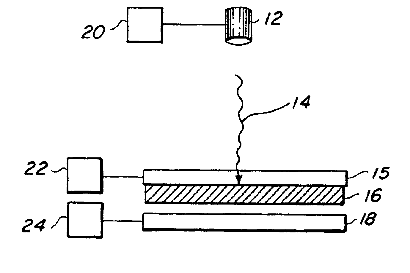
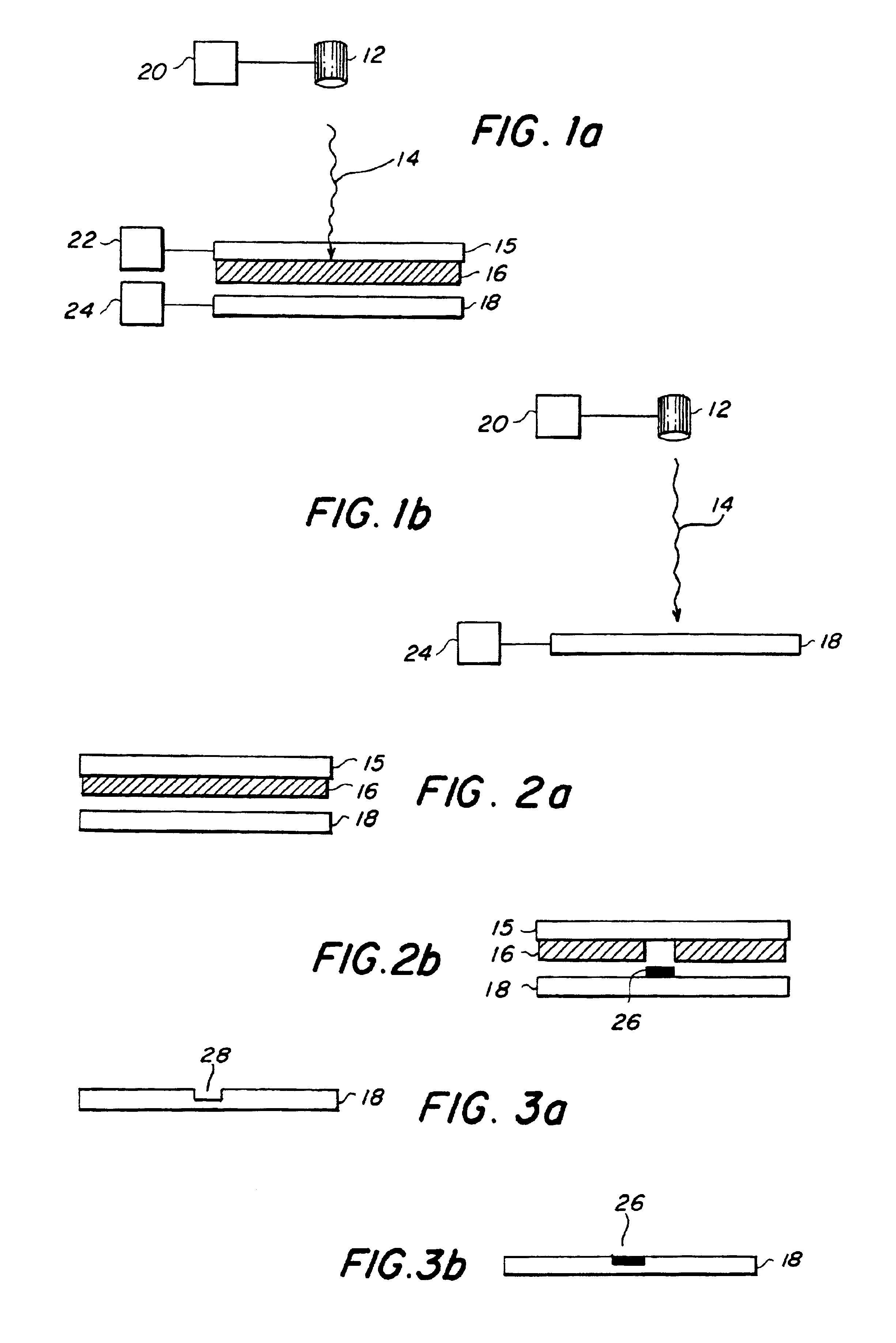
[0078]Creation of a microarray of bovine serum albumin (BSA)—The transfer material was active, biotinylated BSA. The matrix material was a 40% solution of glycerol in 50 mM Tris buffer. The receiving substrate 18 was a nitrocellulose coated slide. The protein was at a concentration of 250 μg / μL solution. In order to passivate the quartz ribbon, 100 nL of the protein solution was spread evenly over a 20 mm2 area of the quartz ribbon. Then a 200 nL aliquot of the protein solution was spread on top of the pre-exposed area of the ribbon. The laser was an ArF excimer, emitting 30 ns pulses of 193 nm energy. The energy density ranged from 50 to 200 mJ / cm2 and the laser was focused to a spot of 150×100 μm2. The viability of the transferred array was verified through fluorescent detection by exposing deposited protein to Cy-5-labeled streptavidin. The other active sites on the slide were first blocked with non-biotinylated BSA to limit background fluorescence. Fluorescence at 635 nm was obs...

example 2

[0079]Creation of a Microarray of Anti-BSA—The transfer material was active, anti-BSA. The matrix material was a 40% solution of glycerol in 50 mM Tris buffer. The receiving substrate 18 was a nitrocellulose coated slide. The antibody was at a concentration of 250 μg / μL solution. In order to passivate the quartz surface, 100 nL of the antibody solution was spread evenly over a 20 mm2 area of the quartz ribbon. Then a 200 nL aliquot of antibody solution was spread on top of the pre-exposed area of the ribbon. The laser was an ArF excimer emitting 30 ns pulses of 193 nm energy. The energy density ranged from 50 to 200 mJ / cm2 and the laser was focused to a spot of 150×100 μm2. The viability of the transferred antibody array was verified through fluorescent detection. The other active sites on the nitrocellulose slides were first blocked with AAA. The array was then exposed to biotinylated BSA, followed by a treatment of Cy-5-labeled streptavidin. Fluorescence at 635 nm was observed fro...


PUM

PropertyMeasurementUnit
temperatureaaaaaaaaaa
thickaaaaaaaaaa
sizeaaaaaaaaaa

Abstract

A method for creating a microarray of biomaterial uses a source of laser energy, a receiving substrate, and a target substrate. The target substrate comprises a laser-transparent support having a laser-facing surface and a support surface. The target substrate also comprises a composite material having a back surface in contact with the support surface and a front surface. The composite material comprises a mixture of the biomaterial to be deposited and a matrix material. The matrix material is a material that has the property that, when it is exposed to laser energy, it desorbs from the laser-transparent support. The source of laser energy is positioned in relation to the target substrate so that laser energy is directed through the laser-facing surface of the target substrate and through the laser-transparent support to strike the composite material at a defined target location. The receiving substrate is positioned in a spaced relation to the target substrate. The source of laser energy has sufficient energy to desorb the composite material at the defined target location, causing the composite material to desorb from the defined target location and be lifted from the support surface of the laser-transparent support. The composite material is deposited at a defined receiving location on the receiving substrate. The steps are repeated at successive defined target locations and successive defined receiving locations such that the composite material is deposited in a microarray of deposited composite material. The method is useful for creating, for example, a gene recognition array,

Description

[0001]This nonprovisional application is a continuation-in-part application of U.S. patent application Ser. No. 09 / 671,166 filed on Sep. 28, 2000, now U.S. Pat. No. 6,766,764 which is a divisional application of U.S. Ser. No. 09 / 318,134, now U.S. Pat. No. 6,177,151 filed on May 25, 1999, which claims benefit of U.S. provisional patent application 60 / 117,468 filed on Jan. 27, 1999. This application also claims benefit of U.S. provisional patent application 60 / 269,384 filed on Feb. 20, 2001 as to certain matter. All applications and patents named above are incorporated herein by reference.BACKGROUND OF THE INVENTION[0002]1. Field of the Invention[0003]The invention relates generally to a method for creating a microarray of biomaterial by direct writing of a wide range of different biomaterials onto a substrate.[0004]2. Description of the Prior Art[0005]The term “direct write” refers generally to any technique for creating a pattern directly on a substrate, either by adding or removing...

Claims


Application Information

Patent Timeline
Patent Type & Authority Patents(United States)
IPC IPC(8): B01J19/00C23C14/04C23C14/28H05K3/02H05K3/04C07B61/00C40B40/18C40B60/14
CPCB01J19/0046B82Y30/00C23C14/048C23C14/28H05K3/046B01J2219/00317B01J2219/00441B01J2219/00527B01J2219/00585B01J2219/0059B01J2219/00596B01J2219/00605B01J2219/00612B01J2219/00626B01J2219/00659B01J2219/00677B01J2219/00689B01J2219/0072B01J2219/0074B01J2219/00745B01J2219/0075C40B40/18C40B60/14G01N2001/2886
Inventor RINGEISEN, BRADLEY R.CHRISEY, DOUGLAS B.PIQUE, ALBERTOMCGILL, R. ANDREWKRIZMAN, DAVID
Owner UNITED STATES OF AMERICA
Why Eureka
Try Eureka