
Silver salt photothermographic dry imaging material, image recording method and image forming method for the same

a technology of dry imaging and silver salt, which is applied in the direction of diffusion transfer process, photosensitive materials, instruments, etc., can solve the problems of insufficient levels in terms of realizing stable silver color tone, difficult to control developed silver shapes and maintain images, etc., to achieve excellent image color tone and silver image stability, and low photographic fog

Inactive Publication Date: 2006-02-28
KONICA MINOLTA INC
View PDF3 Cites 8 Cited by
  • Summary
  • Abstract
  • Description
  • Claims
  • Application Information

AI Technical Summary

Benefits of technology

[0484]Also, it is possible to use the polymer of which equilibrium water content at 25° C. and at the relative humidity of 60% is 2% or less by mass as the binder within the range where the effects of the invention are not impaired. More preferably the equilibrium water content is from 0.01 to 1.5%, and still preferably from 0.02 to 1% by mass. For the definition of and the method for measuring the water content, it is possible to refer to, for example, Kobunshi Kogaku Koza 14, Kobunshi Zairyo Sikenho (edited by Society of Polymer Science, Japan, Chijinshokan).
[0485]In the present invention, it is well known that the use of a crosslinker for the above binder improves film adherence and reduces development unevenness, and there are also effects that the photographic fog in storage and the production of printout silver after the development are inhibited.
[0486]As the crosslinkers used in the invention, it is possible to use various crosslinkers used as photographic materials in earlier technology such as aldehyde, epoxy, ethyleneimine, vinylsulfone, sulfonate ester, acryloyl, carbodiimide, and silane type crosslinkers described in JP-A-50-96216, but preferred are isocyanate, silane, epoxy type compounds or acid anhydride shown below.
[0487]The above isocyanate type crosslinkers are isocyanates and addition bodies (adduct bodies) thereof having at least two isocyanate groups, and further specifically include aliphatic diisocyanates, aliphatic diisocyanates having cyclic groups, benzene diisocyanates, naphthalene diisocyanates, biphenyl isocyanates, diphenylmethane diisocyanates, triphenylmethane diisocyanates, triisocyanates, tetraisocyanates, addition bodies of these isocyanates and addition body of these isocyanates with bivalent or trivalent polyalcohol.
[0488]As specific examples, it is possible to utilize isocyanate compounds described in pages 10 to 12 of JP-56-5535.
[0489]Besides, the addition body of isocyanate and polyalcohol especially improves interlayer adhesiveness, and is high in ability to prevent occurrences of interlayer peeling, displacement of images and cells. Such isocyanate may be placed in any parts of photothermal photographic materials. For example, in a support (especially, when the support is paper, it can be contained in the size composition thereof), it can be added to any layer of the photosensitive layer side of the support such as the photosensitive layer, surface protection layer, intermediate layer, anti-halation layer and under coating layer, and can be added to one or two or more layers of these layers.

Problems solved by technology

A silver ion reducing agent, a compound which forms a complex with silver ions, and a compound which bleaches fine silver nuclei which are sources of photographic fog produced on the surface of silver halide grains are contained in the silver salt photothermographic dry imaging material, and it is not easy to control developed silver shapes and maintain the image thereof after the thermal development.
Also, proposed are the improvement methods by activating photothermographic property by contrivance of fatty acid silver salt crystal structures (e.g., see Patent References 3 and 4), but it can not help being said that all methods are at insufficient levels in terms of realizing the stable silver color tone.
However, the technology described in Patent Reference 5 is more excellent in improvement level of the color tone compared to the above technology which controls the developed silver shape, but has disadvantages that the photographic fog and deterioration of the color tone changes frequently occur at the long term storage and at the image storage probably because produced dyestuffs are unstable and further adversely affect the silver halide.
In these technologies, improvement of covering power enhancement is observed, but they also have faults.
Thus, it has been difficult to simultaneously control the covering power enhancement and image color tone.
The improvement by coupler type coloring dyestuffs is disclosed (e.g., see Patent Reference 12), but the color tone control is difficult, slight deviance of the color tone occurs in every process, and reproducibility is poor.
Furthermore, when numerous fine silver clusters are present, so-called image storage stability is easily deteriorated such as the case where the imaging material after heating process is exposed under irradiated light.
If residual sensitivity of the photosensitive silver halide after the heating process is low, this effect is reduced, but still it cannot be said that it is a sufficient level, and it is not preferable because the sensitivity at the regular exposure is also reduced.
Or it might be because the fine developed silver per se is unstable for light and heat.
In the meanwhile, there has been problematic in that slipping property between the imaging material and a transport roller or processing members of the thermal developer changes, and transport failure and density unevenness occur.
Also there has been problematic in that the density of the photothermographic imaging material varies with time.
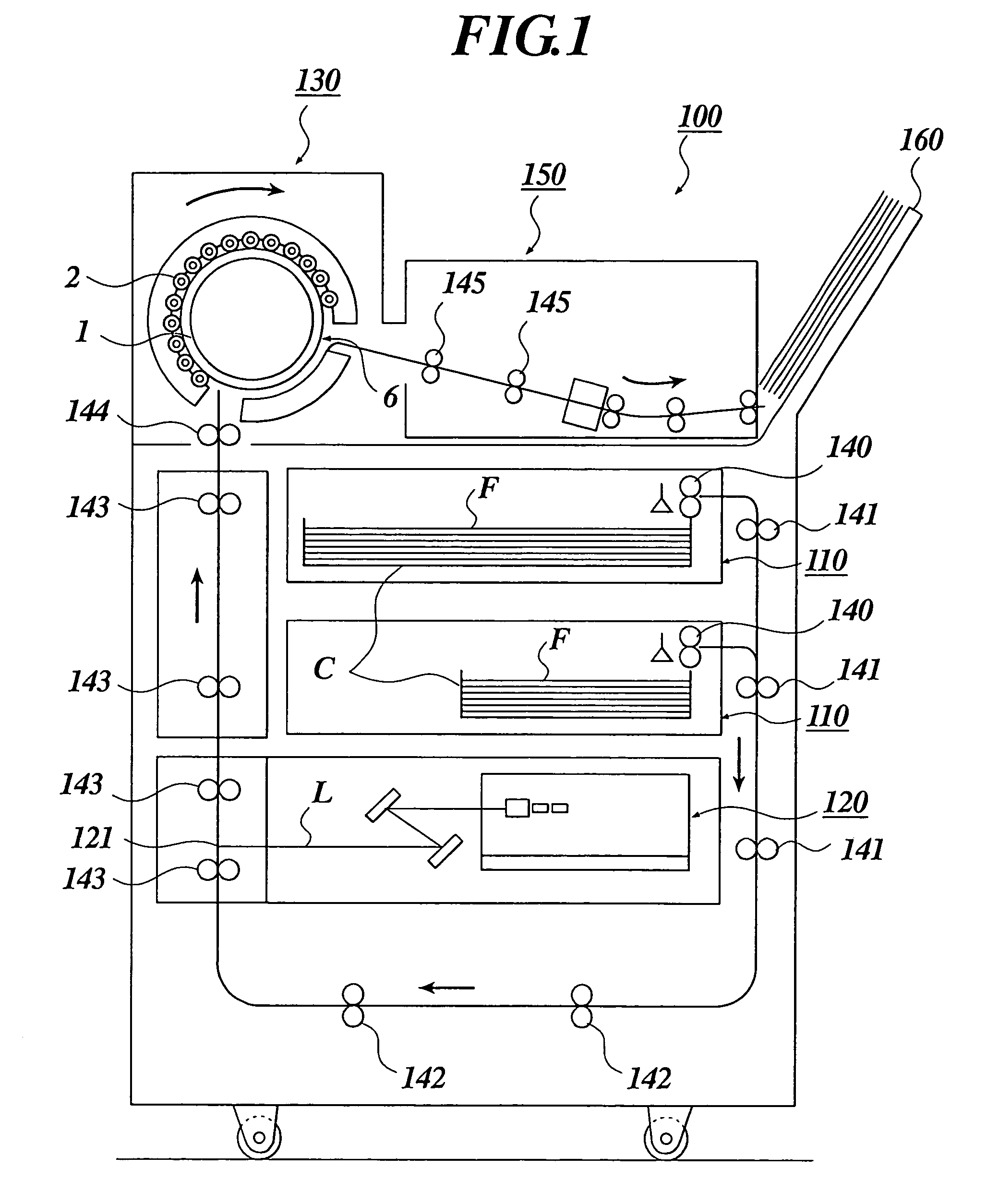
For downsizing the thermal development processing apparatus, it is more advantageous to use a heat drum mode than to use a horizontal transport mode, but there has been problematic in that powder drop off, density unevenness and roller mark easily occur at the thermal development processing.
However, when these technologies were used, there was problematic in that density changes (printout property) with time after the thermal development processing became large and the silver color tone became extremely different compared to wet type X-ray films in earlier technology.

Method used


Image

  • Silver salt photothermographic dry imaging material, image recording method and image forming method for the same
  • Silver salt photothermographic dry imaging material, image recording method and image forming method for the same
  • Silver salt photothermographic dry imaging material, image recording method and image forming method for the same

Examples


example 1

>

[0743]Corona discharge treatment at 0.5 kV.A.min / m2 was given to one side face of a polyethylene terephthalate film base (thickness 175 μm) blue-colored at a density of 0.170, and then using the following under coat coating solution A, an under coating layer a was applied on it such that the thickness of dried film became 0.2 μm. The corona discharge treatment at 0.5 kV.A.min / m2 was similarly given to another face, and then using the following under coat coating solution B, an under coating layer b was applied on it such that the thickness of dried film became 0.1 μm. Subsequently, heat treatment was carried out at 130° C. for 15 min in a heat treating type oven having a film transport apparatus made up of multiple roller groups to make a support.

(Preparation of Under Coat Coating Solution A)

[0744]Copolymer latex solution (270 g) of 30% of n-Butyl acrylate, 20% of t-butyl acrylate, 25% of styrene and 25% of hydroxyethyl acrylate by mass (solid content 30%), 0.6 g of surfactant (UL-...

example 2

>

[0795]Polyethylene terephthalate with an intrinsic viscosity IV=0.66 (measured in phenol / tetrachloroethane=6 / 4 (mass ratio) at 25° C.)(hereinafter abbreviated as PET) was obtained using terephthalic acid and ethyleneglycol according to the standard method. This was pelletized, then dried at 130° C. for 4 hours, melted at 300° C., then extruded from a T type die, and rapidly cooled to make an undrawn film with a thickness such that a film thickness after heat setting is 175 μm.

[0796]This undrawn PET film was vertically drawn to 3.3 times using rollers with different periphery velocity, and then horizontally drawn to 4.5 times using a tenter. At that time, the temperatures were 110° C. and 130° C., respectively. Subsequently, this was heat-set at 240° C. for 20 sec, and relaxed by 4% in a horizontal direction at the same temperature. Subsequently, after slitting a chock portion of the tenter, a knurling was given at both ends, and the film was rolled up at 40 N / cm2 to yield a roll-sh...

example 3

>

[0854]Corona discharge treatment at 0.5 kV·A·min / m2 was given to one side face of a polyethylene terephthalate film base (thickness 175 μm) blue-colored at a density of 0.170, and then using the following under coat coating solution A, an under coating layer a was applied on it such that the thickness of dried film became 0.2 μm. The corona discharge treatment at 0.5 kV·A·min / m2 was similarly given to another face, and then using the following under coat coating solution B, an under coating layer b was applied on it such that the thickness of dried film became 0.1 μm. Subsequently, heat treatment was carried out at 130° C. for 15 min in a heat treating type oven having a film transport apparatus made up of multiple roller groups to make a support.

(Preparation of Under Coat Coating Solution A)

[0855]Copolymer latex solution (270 g) of 30% of n-Butyl acrylate, 20% of t-butyl acrylate, 25% of styrene and 25% of hydroxyethyl acrylate by mass (solid content 30%), 0.6 g of surfactant (UL-...


PUM

PropertyMeasurementUnit
RHaaaaaaaaaa
mean particle sizeaaaaaaaaaa
non-photosensitiveaaaaaaaaaa

Abstract

A silver salt photothermographic dry imaging material including non-photosensitive aliphatic carboxylic acid silver salts; a photosensitive emulsion containing photosensitive silver halide grains; a silver ion reducing agent; a binder; and a cyan coloring leuco dye. A percentage of the photosensitive silver halide grains having a mean particle size of 0.01 or more μm and 0.04 μm or less is 5% or more by mass and 50% or less by mass of total photosensitive silver halide grains by conversion into a silver amount.

Description

BACKGROUND OF THE INVENTION[0001]1. Field of the Invention[0002]The present invention relates to a silver salt photothermographic dry imaging material (hereinafter, also referred to as “photothermographic imaging material”) with low photographic fog, high sensitivity and high maximum density, which are good in color tone and excellent in rapid thermal development suitability, and an image recording method and an image forming method using the same.[0003]Further, The present invention relates to a photothermographic imaging material, and particularly a photothermographic imaging material with high density which are excellent in light radiated image stability, silver color tone, changes of silver color tone with time, density unevenness at thermal development and image storage stability in storage at room temperature.[0004]2. Description of Related Art[0005]Recently, in the fields of medical care and print plate making, waste solutions involved in wet processing of image formation mat...

Claims


Application Information

Patent Timeline
Patent Type & Authority Patents(United States)
IPC IPC(8): G03C1/00G03C1/005G03C1/494G03C5/16G03C1/09G03C1/498G03C5/02
CPCG03C1/09G03C1/49809G03C1/49818G03C1/49845G03C1/49863G03C1/498Y10S430/146G03C1/49881G03C5/02G03C7/3041G03C2001/091G03C2001/096G03C2001/097G03C2001/098G03C2007/3025G03C2200/36G03C2200/39
Inventor KASHIWAGI, HIROSHIGOTO, NARITO
Owner KONICA MINOLTA INC
Learn More