Magnetic field sensor utilizing ferromagnetic nanometer ring strong magnetic resistance effect

A magnetic field sensor and giant magnetoresistance technology, applied in instruments, measuring magnetic variables, measuring devices, etc., can solve the problems of small output signal amplitude, difficulty in ensuring consistency, small output signal, etc., to achieve large changes in magnetoresistance, production Simple, large output signal effect

Inactive Publication Date: 2009-02-11
UNIV OF SCI & TECH BEIJING
View PDF0 Cites 10 Cited by
  • Summary
  • Abstract
  • Description
  • Claims
  • Application Information

AI Technical Summary

Problems solved by technology

[0003] At present, the widely used magnetic sensors include anisotropic magnetoresistance sensor, spin valve giant magnetoresistance sensor, magnetic tunnel junction giant magnetoresistance sensor, etc. Anisotropic magnetoresistance sensor has small output signal and high noise due to the small magnetoresistance of the material. Large; the magnetic field sensitivity of the spin valve giant magnetoresistance sensor is significantly improved compared with the anisotropic magnetoresistance sensor, which can reach 1% / Oe, but the total magnetoresistance change is only 2-5%, and the output signal amplitude is not large; Compared with the previous two sensors, the magnetic tunnel junction giant magnetoresistance sensor requires higher preparation technology, and needs to prepare an ultra-thin and uniform insulating layer of 1 nanometer, and it is difficult to ensure its consistency in mass production.

Method used


Image

  • Magnetic field sensor utilizing ferromagnetic nanometer ring strong magnetic resistance effect
  • Magnetic field sensor utilizing ferromagnetic nanometer ring strong magnetic resistance effect
  • Magnetic field sensor utilizing ferromagnetic nanometer ring strong magnetic resistance effect

Examples


Embodiment 1

[0018] A magnetic field sensor composed of cobalt-iron alloy ferromagnetic nano-rings and copper measuring leads was fabricated on a quartz glass substrate.

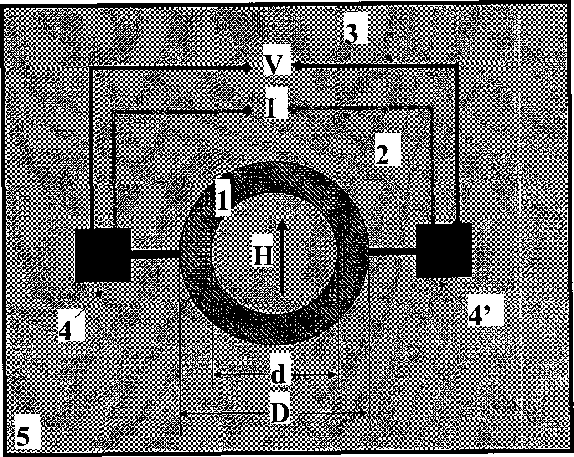
[0019] The first step is to first select the quartz glass substrate 5, cut it to a size of 10 mm in length, 10 mm in width, and 0.5 mm in thickness, ultrasonically clean it with acetone, then ultrasonically clean it with deionized water, and finally clean it with absolute ethanol ultrasonically, and then clean it with high-purity nitrogen gas. Blow dry and set aside; the second step is to prepare the cobalt-iron alloy ferromagnetic nano-ring 1 on the substrate, put the substrate into the coating chamber of the magnetron sputtering coating equipment, and pump the coating chamber to 2×10 -5 The vacuum degree of Pascal is deposited on the substrate with a magnetron sputtering method to deposit a 40-nanometer thick cobalt-iron alloy film, and the working gas is argon gas of 0.8 Pascal, which is then taken out and coated on th...

Embodiment 2

[0023] A magnetic field sensor composed of cobalt metal magnetic nano-rings and copper-gold alloy measuring leads is fabricated on a single crystal silicon substrate.

[0024] The first step is to select a single crystal silicon substrate 5 and cut it to a size of 10 mm in length, 10 mm in width and 0.5 mm in thickness, ultrasonically clean it with acetone, then ultrasonically clean it with deionized water, and finally clean it with absolute ethanol ultrasonically. Blow dry with nitrogen and set aside; the second step is to prepare cobalt metal ferromagnetic nano-ring 1 on the substrate, put the substrate into the coating chamber of the magnetron sputtering coating equipment, and pump the coating chamber to 2×10 -5 The vacuum degree of Pascal is deposited on the substrate with a magnetron sputtering method to deposit a 40-nanometer thick cobalt metal film, and the working gas is argon gas of 0.8 Pascal, which is then taken out and coated on the deposited film with photoresist. ...

Embodiment 3

[0028] A magnetic field sensor composed of chromium dioxide ferromagnetic nano-rings and copper-zinc alloy measuring leads was fabricated on a single crystal silicon substrate.

[0029]The first step is to select a single crystal silicon substrate 5 and cut it to a size of 10 mm in length, 10 mm in width and 0.5 mm in thickness, ultrasonically clean it with acetone, then ultrasonically clean it with deionized water, and finally clean it with absolute ethanol ultrasonically. Blow dry with nitrogen and set aside; the second step is to prepare chromium dioxide ferromagnetic nano-ring 1 on the substrate, put the substrate into the coating chamber of the pulse laser coating equipment, and pump the coating chamber to 1×10 -7 The vacuum degree of Pascal, irradiate the chromium target with pulsed laser, pass through the oxygen of 400mTorr, deposit a chromium dioxide film with a thickness of 40 nanometers on the substrate, then take it out, coat the deposited film with photoresist, and ...


PUM


Abstract

The invention provides a magnetic field sensor utilizing the giant magnetoresistive effect of a ferromagnetic nano-ring, and belongs to the technical field of magnetic nano-sensors. The sensor is composed of a ferromagnetic nano-ring prepared on a substrate of nanometer size and a group of lead wires; the group of lead wires connected to the two ends of the ring also serve as a constant current source connecting wire and a voltage measurement connecting wire; the outside diameter D of the ferromagnetic nano-ring is 7 nm-10 um; the inside diameter d is smaller than the outside diameter D; the width of the ring is 5 nm-1 um; and the thickness of the nano-ring is 1 nm-500 nm. The sensor utilizes the ferromagnetic nano-ring under the action of the outside magnetic field, and the resistance the ferromagnetic nano-ring changes greatly, so as to detect the change of the outside magnetic field; the manufacture is very simple; the output signal is large; and the response is fast. The sensor is especially applicable to the detection of the threshold value of the magnetic field change; besides, the magnetic field sensitivity of the magnetic field transformation point can reach 2-10 percent/Oe or is higher than 2-10 percent/Oe, and the sensor also can serve as a magnetic cell.

Description

technical field [0001] The invention belongs to the technical field of magnetic nanometer sensors, in particular to a magnetic field detection sensor using a ferromagnetic nanoring structure material. Background technique [0002] Magnetic field detection is one of the important aspects of magnetic measurement, and it has a wide range of applications in the national economy, such as the magnetic recording readout head in the information industry, the measurement of the geomagnetic azimuth in navigation, the measurement of the magnetic field azimuth on the aircraft, and the size of the geomagnetic field in oil exploration. and orientation measurement, measurement of magnetic flux leakage and remanence in industrial production, non-destructive testing of product quality in metallurgy and aviation industry, application of weak magnetic anti-counterfeiting technology, etc., the existing technology mainly uses anisotropic magnetoresistance materials, Such as NiFe, NiCo and other ...

Claims


Application Information

Patent Timeline
Patent Type & Authority Applications(China)
IPC IPC(8): G01R33/09
Inventor 潘礼庆向睿阴津华徐美黄筱玲田跃侯志坚邱红梅赵雪丹秦良强王凤平
Owner UNIV OF SCI & TECH BEIJING
Why Eureka
Try Eureka