Pressure strain device manufactured by sputtering silicon film with ion beams and method thereof

A technology of ion beam sputtering and silicon thin film, which is applied in the field of ion beam sputtering silicon materials to manufacture the core components of pressure sensors and pressure strain devices. It can solve the problems of long sputtering time, low sensitivity coefficient, and poor long-term stability. The effect of simple process, high sensitivity and strong adhesion

Inactive Publication Date: 2011-09-07
东莞市百赛仪器有限公司
View PDF9 Cites 13 Cited by
  • Summary
  • Abstract
  • Description
  • Claims
  • Application Information

AI Technical Summary

Problems solved by technology

It is well known that there are many deficiencies and shortcomings in the product performance of this type of technology: it is reflected in the fact that the glue is easy to age over time, resulting in a decrease in insulation performance, unstable bond strength, resulting in sensor creep, poor long-term stability, etc., especially in harsh environments such as high temperature and high temperature. Especially in wet and high-frequency pressure conditions; another significant disadvantage of metal foil strain gauges is low sensitivity, and its sensitivity coefficient is only 1 to 2 millivolts per volt; in the production process, repeatability is caused by the need for manual pasting. and poor consistency and inefficiencies in scale production
[0007] At present, ion beam sputtering deposited thin films are mainly used in traditional metal strain materials such as nickel-chromium alloy thin films, and its low sensitivity coefficient still exists. The low sensitivity coefficient of the strain gauge will inevitably require a higher output strain when the sensor elastic element is designed. , which will inevitably reduce the sensor's fatigue resistance and high overload impact resistance, and these are the performance requirements that modern industrial applications expect from sensors
[0008] In addition, when using the ion beam sputtering deposition thin film process to use metal materials as elastic components, it is necessary to make an electrical insulating layer to electrically isolate the strain layer from the base of the metal elastic component. The usual method is still...

Method used


Image

  • Pressure strain device manufactured by sputtering silicon film with ion beams and method thereof
  • Pressure strain device manufactured by sputtering silicon film with ion beams and method thereof
  • Pressure strain device manufactured by sputtering silicon film with ion beams and method thereof

Examples


Embodiment Construction

[0038] In order to further illustrate the method of the present invention, a preferred embodiment of the present invention will now be described in detail. However, the embodiment is only for illustration and explanation, and cannot be used to limit the scope of patent protection of the present invention.

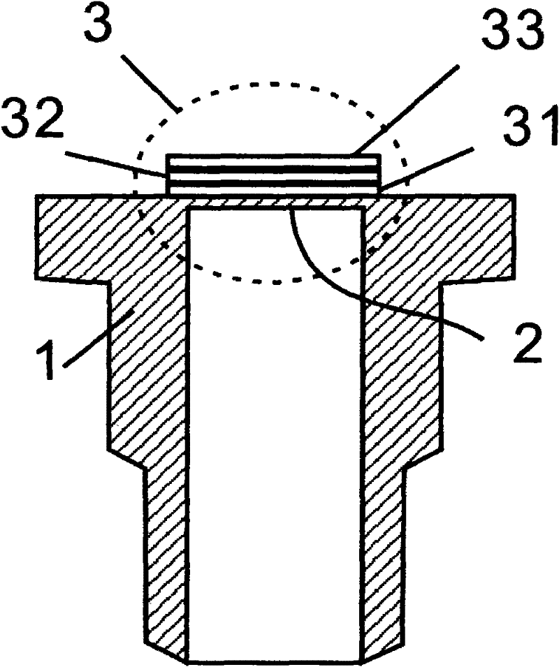
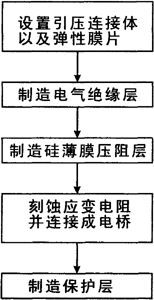
[0039] Such as Figure 1 ~ Figure 3 Shown is a pressure strain device and method made by ion beam sputtering silicon thin film, said method comprising the following steps:

[0040] ①, first set up a pressure introduction connector 1, and a metal elastic diaphragm 2 made together with the pressure introduction connector 1;

[0041] Then on the metal elastic diaphragm 2, the electrical isolation layer of the first layer is made by printing the insulating dielectric paste or by sputtering the insulating material;

[0042] ②, and then on the electrical isolation layer, apply ion beam sputtering deposition method to manufacture silicon thin film, and make the second layer as si...


PUM


Abstract

The invention relates to a pressure strain device manufactured by sputtering a silicon film with ion beams and a method thereof. The method comprises the following steps: firstly arranging a lead pressure connector and a metal elastic film integrated with the lead pressure connector; forming a first electric isolating layer on the metal elastic film by using a printing sintering method or sputtering method; forming a silicon film piezoresistive layer on the electric isolating layer by using an ion beam sputtering deposition method; etching a strain gage physical shape structure on the silicon film piezoresistive layer by using a superfine etching technology; and coating a medium sizing material on the piezoresistive layer to form a protection layer. According to the method, the pressure strain device is manufactured by sputtering the silicon film with ion beams and the silicon material is deposited layer by layer in nanometer scale, the formed film has excellent compactness and stability and the manufactured pressure strain device has high sensitivity, long service life and excellent stability. The process for manufacturing the electric isolating layer by adopting the printing sintering method is convenient, has high yield and is suitable for mass production.

Description

technical field [0001] The invention relates to a product manufacturing technology of a pressure sensor, in particular to a technical method for manufacturing a core component of a pressure sensor, that is, a pressure strain device, by ion beam sputtering silicon material. Background technique [0002] As a key device in the modern information industry, the pressure sensor's characteristics and uses mainly depend on the technology and process of its core component sensitive components. [0003] With the continuous development of modern industrial technology, the technology of sensitive components is changing with each passing day, which is mainly reflected in the use of elastomer components with different mechanical structures, or the use of various new materials, or the use of various new technology and means, and even based on innovation The physical principle and so on. [0004] Technologies and products based on metal resistance strain effect or semiconductor piezoresis...

Claims


Application Information

Patent Timeline
IPC IPC(8): G01L1/22G01L9/04C23C14/46C23C14/14
Inventor 欧阳德利
Owner 东莞市百赛仪器有限公司
Why Eureka
Try Eureka