
Sludge treatment method

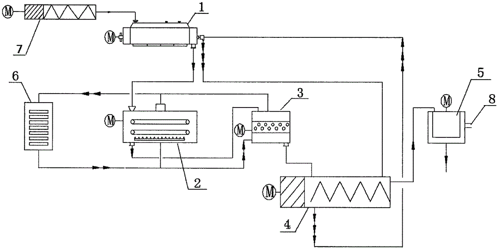
A kind of sludge treatment and sludge technology, which is applied in biological sludge treatment, water/sludge/sewage treatment, sludge treatment through temperature control, etc., can solve the problem of low water removal rate between sludge cells, and avoid The generation of internal colloidal particles, the improvement of dehydration performance, and the effect of cooling and easing

Active Publication Date: 2017-02-01
广东华大纵横环保科技有限公司
View PDF2 Cites 3 Cited by
  • Summary
  • Abstract
  • Description
  • Claims
  • Application Information

AI Technical Summary

Problems solved by technology

The traditional dehydration process can only remove free water and part of interstitial water, and the removal rate of interstitial water in sludge cells is very low

Method used


Image

  • Sludge treatment method

Examples


Embodiment 1

[0025] Preparation of grinding balls: Mix silicon dioxide, boron oxide, yttrium oxide, magnesium oxide, and boron oxide to obtain a mixed powder; then melt the mixed powder at 1500°C for 1 hour, and quench to obtain a block; crush the block and pass 325-mesh standard sieve to obtain ceramic powder; then mix the ceramic powder with lime and press the ball; finally sinter at 950°C for half an hour and then sinter at 1200°C for 1 hour to obtain the ceramic body; butyl acrylate, N-methylol Acrylamide, styrene and isomeric tridecyl alcohol polyoxyethylene ether are added to water to form an emulsion; then potassium persulfate aqueous solution is added dropwise, and reacted at 70-75°C for 1.5-2 hours to obtain an inert polymer slurry. Disperse the ceramic body in ethanol, then add inert polymer slurry; mix for 2 hours, then add maleic anhydride and diethyl phosphite; continue mixing for 2 hours; then remove the solvent, and then treat at 120-135°C for 20 Minutes, that is, the outer ...

Embodiment 2

[0028] Using the grinding balls of Example 1 for sludge dewatering: the municipal sludge with a water content of 80% is transported to the sludge cooler by the sludge pump, and the sludge cooler adopts paddle-type cooling equipment to indirect heat exchange. The sludge is cooled and cooled, and the cooling medium comes from the conveying screw. After heat exchange and cooling, the temperature of the sludge drops from normal temperature to 10°C. The sludge cooled from the paddle cooler enters the belt freezer. In the belt freezer, the low-temperature cooling gas enters the freezer from the bottom and directly contacts the sludge, and the temperature of the sludge decreases. As the sludge is conveyed on the belt, the temperature of the sludge is further reduced. According to the different properties of the sludge, the temperature of the sludge is controlled at -5°C when it is discharged from the freezer. As the temperature of the sludge decreases, the structure of the sludge als...


PUM


Abstract

The invention discloses a sludge treatment method. The sludge treatment method comprises: firstly, preparing grinding balls and conveying sludge to be treated to a cooler; then, adjusting the temperature of the sludge to 5 DEG C to 10 DEG C; then conveying the sludge into a refrigerator and adjusting the temperature of the sludge to -10 DEG C to -5 DEG C; then conveying the freezed sludge into a ball mill and carrying out ball milling on the sludge in cooling gas; conveying the sludge, which is subjected to the ball milling, to a centrifugal machine through utilizing a conveying spiral; after centrifuging and separating, removing clear liquid to finish refrigeration, wall breaking and dehydration of the sludge. According to the sludge treatment method, a sludge refrigeration and wall breaking process is disclosed for the first time, sludge cell walls are broken through a refrigeration method and a colloidal structure in the sludge is damaged, so that a moisture distribution condition in the sludge is changed; breaking requirements of releasing needed sludge cells by interstitial water in the sludge cells are met, so that dehydration performance of the sludge is improved, and defects of an existing dehydration process that only free water and one part of the interstitial water can be removed are overcome.

Description

technical field [0001] The invention relates to the technical field of sewage treatment, in particular to a sludge treatment method. Background technique [0002] Sludge is a solid waste produced in the process of sewage treatment. With the development of domestic sewage treatment business, the total water treatment volume and treatment degree of sewage plants will continue to expand and improve, and the amount of sludge produced will also increase day by day. The investment in sludge treatment The cost of sludge treatment accounts for 20% to 50% of the operating cost of the sewage treatment plant, which brings a heavy burden to the sewage treatment plant. Sewage sludge contains not only a large amount of organic matter and nutrients such as nitrogen and phosphorus, but also toxic and harmful components such as heavy metals, pathogenic bacteria and parasites. In order to prevent secondary pollution caused by sludge and ensure the normal operation and treatment effect of sew...

Claims


Application Information

Patent Timeline
Patent Type & Authority Applications(China)
IPC IPC(8): C02F11/12C02F11/20C02F11/02
CPCC02F11/02C02F11/12C02F11/20C02F2303/06
Inventor 彭代信苏艳丽
Owner 广东华大纵横环保科技有限公司
Learn More