
Multicomponent protein microarrays

a protein microarray and multi-component technology, applied in the field of protein microarrays, can solve the problems of reducing protein stability, limiting signal-to-noise levels, and time-consuming and costly efforts

Inactive Publication Date: 2005-03-10
MCMASTER UNIV
View PDF5 Cites 23 Cited by
  • Summary
  • Abstract
  • Description
  • Claims
  • Application Information

AI Technical Summary

Benefits of technology

A third system involving protein-peptide interactions consisted of rhodamine-labelled calmodulin (CaM) and rhodamine-labelled mellitin, and was based on a slightly different fluorescence-based screening method utilizing these same biomolecules entrapped in sol-gel derived monoliths. In the absence of antagonists or denaturants (such as guanidine hydrochloride), these two species exist in a complex that brings the two rhodamine labels into close proximity, resulting in self-quenching and thus a low fluorescence signal. Upon addition of the denaturant guanidine hydrochloride the complex was dissociated, resulting in separation of the two probes and a resultant enhancement in fluorescence intensity. Washing of the array resulted in recovery of the intact complex, and hence a lowering of the fluorescent signal, indicating that such a configuration is reversible. Addition of non-antagonists such as benzamidine (negative control) resulted in no changes in intensity above that obtained for CaM alone.

Problems solved by technology

Historically, enzyme activity and inhibition studies were conducted by focusing on a single protein at a time, resulting in time consuming and costly efforts.
However, these immobilization methods can result in improper orientation of the protein's active site and monolayer coverage of the surface, which limits signal-to-noise levels, and decreases protein stability with the introduction of an artificial linker.
Affinity capture methods require the expression of several recombinant proteins (e.g. hexahistidine or glutathione S transferase fusion protein) and / or capture agents (e.g. aptamers or antibodies) and still suffer from the inability to immobilize these proteins in an active form due to dehydration.
Furthermore, this method is limited to soluble proteins in most cases.
Another further serious drawback of all of the above methods is that they are designed to allow immobilization of only a single component per array element (i.e., one type of protein per spot), although it is possible to immobilize two proteins in a spot if the two proteins have affinity for one another.
Immobilization of proteins with non-protein based species, such as polymers or fluorophores, or the immobilization of multiple enzymes involved in coupled catalytic reactions is not amenable to these immobilization methods.

Method used


Image

  • Multicomponent protein microarrays
  • Multicomponent protein microarrays
  • Multicomponent protein microarrays

Examples


example 1

Urease and Fluorescein-labelled Dextran

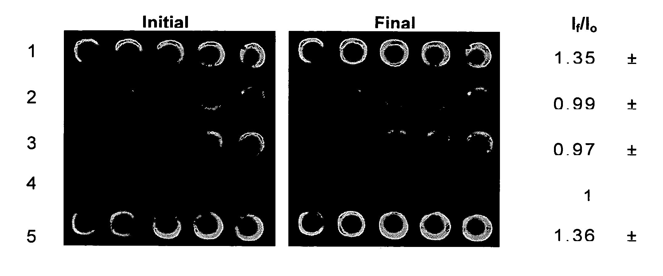
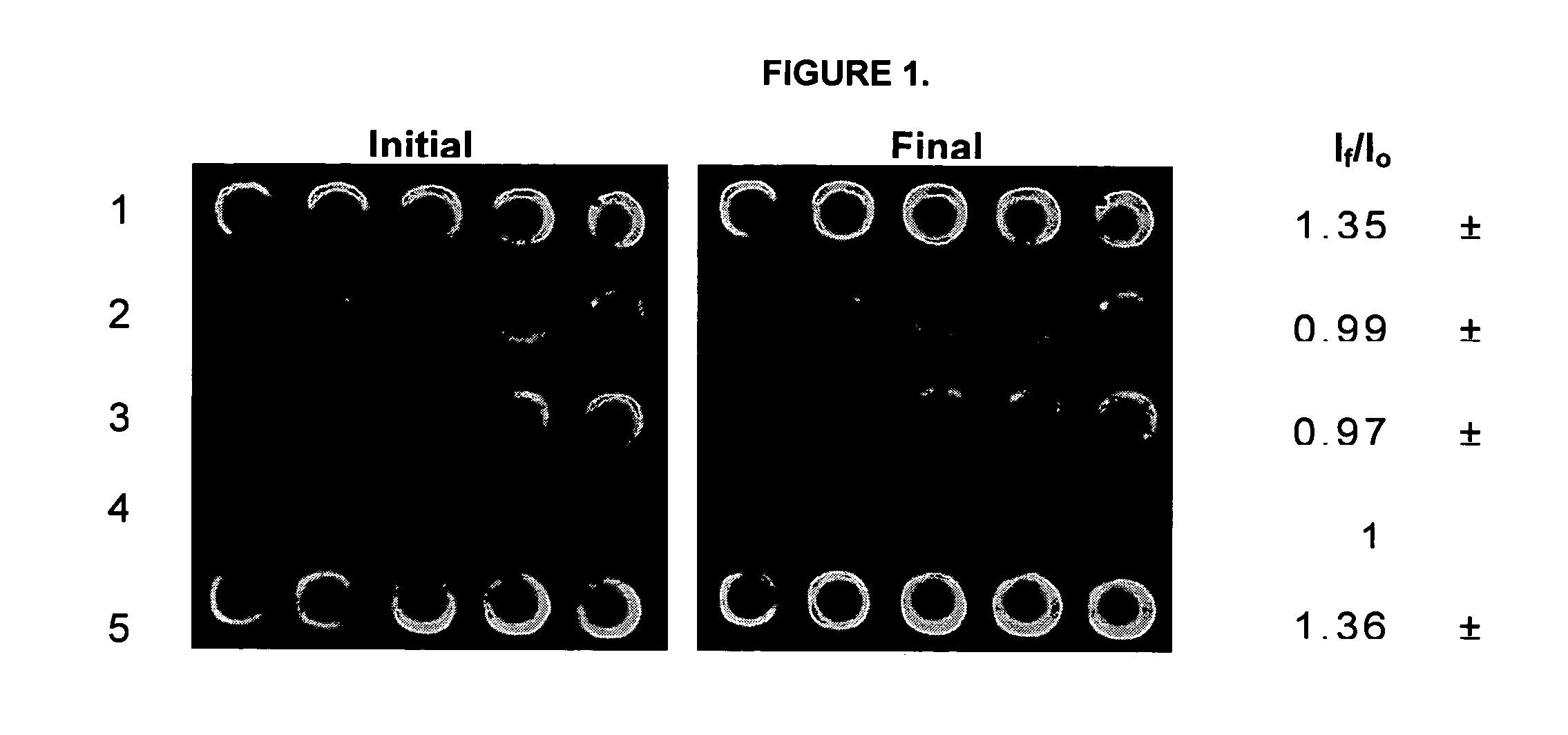
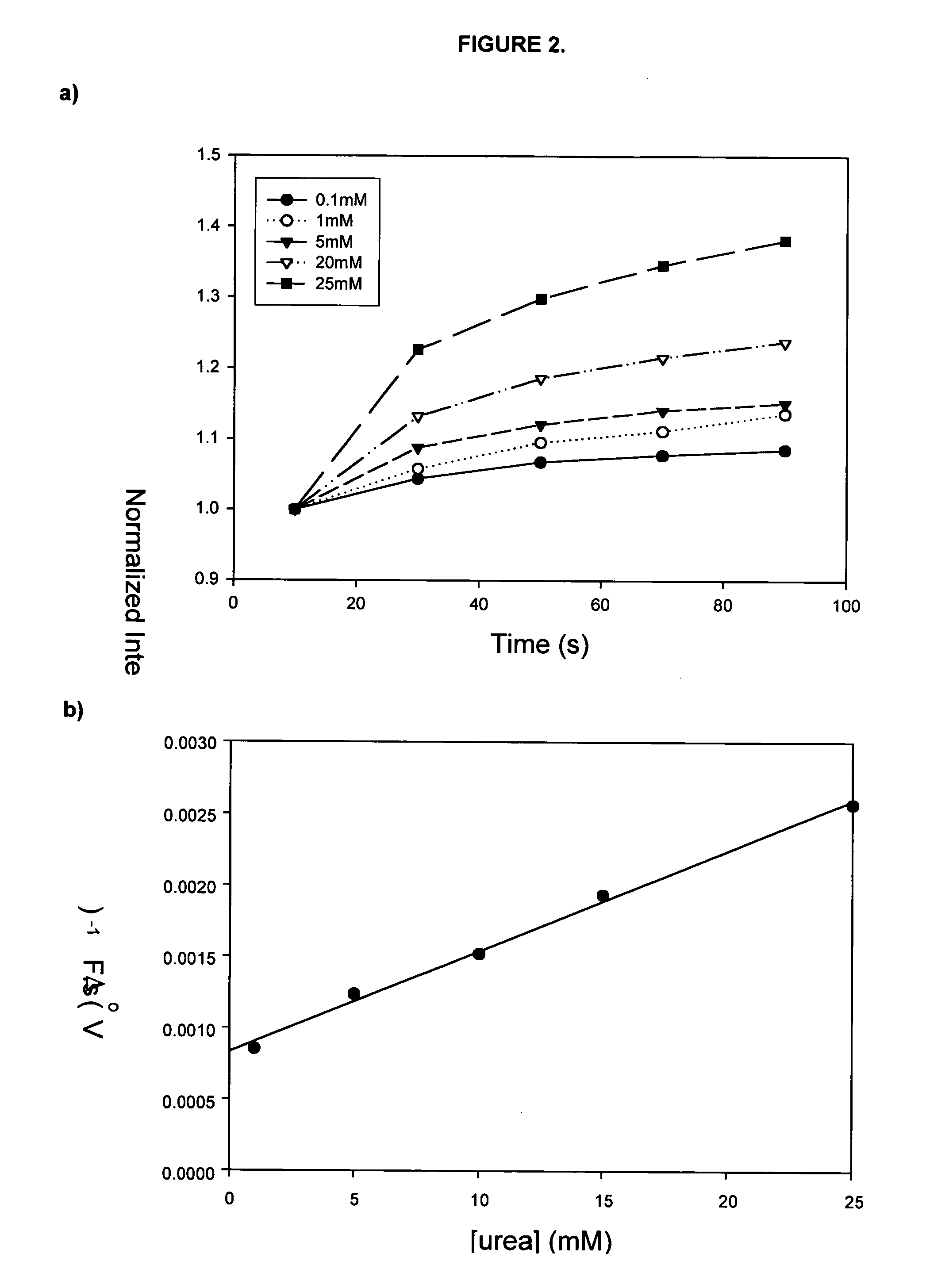
FIG. 1 shows images of a 5×5 microarray that were prepared for kinetic studies of immobilized urease. The array consisted of four different samples, composing a reagentless enzyme assay array that was suitable for sensing of both substrates and inhibitors. In this array, rows 1 and 5 contained urease that was co-immobilized with fluorescein labelled dextran. Also present in the array were a blank row consisting of only sodium silicate with buffer (negative control, row 2), a row containing only fluorescein dextran 70,000 MW as a pH selectivity control to avoid signals related to drifts in pH that were not based on the enzyme catalyzed reaction (row 3), and a row containing AChE with FD as a selectivity control (row 4). These controls ensured that the enhancement of intensity of any spots in the microarray following addition of urea were solely due to the activity and selectivity of the urease and were not due to drifts in pH or autohydrolysis ...

example 2

Glucose Oxidase and Horseradish Peroxidase

The second protein system that was examined in sol-gel derived microarrays was a more complex system, consisting of two proteins that undergo a coupled reaction. Glucose oxidase reacts with D-glucose to form D-gluconolactone and H2O2 (Scheme 1). In the presence of horseradish peroxidase, the H2O2 then reacts with the Amplex Red reagent in a 1:1 stoichiometry to generate the red fluorescent oxidation product, resorufin, as seen in Scheme 1. Resorufin has absorption and fluorescence emission maxima of approximately 563 nm and 587 nm, respectively, at pH>6 [30,31]

FIG. 4 shows a 5×5 array of Glucose Oxidase / Horseradish Peroxidase co-immobilized in sol-gel derived glass. Columns 1 and 5 contain GOx / HRP co-immobilized with Amplex Red (coupled reaction site). Column 2 contains only buffer and Amplex Red and acts as a negative control. Column 3 contains reacted GOx, HRP, glucose and partially reacted Amplex Red and acts as a positive control. Colu...

example 3

Calmodulin-Melittin Array

FIG. 6 shows an array comprised of co-entrapped calmodulin and melittin before and after exposure to a 20:1 molar ratio of guanidine hydrochloride:CaM. Columns 1&5 contain the protein—protein interaction between CaM and Mellitin. Both of which are labelled with rhodamine. Columns 2&4 are blank and contain only buffer. Column 3 contains CaM—Rhodamine alone and acts as a positive control. Upon addition of GdHCl (2M) to the top of the array and imaging every 20s, the CaM-Mel columns increased in fluorescence over 2-fold (Panel B), while the positive control increased slightly initially but reached a relatively low steady-state value quickly (see graph, FIG. 7)

While the present invention has been described with reference to the above examples, it is to be understood that the invention is not limited to the disclosed examples. To the contrary, the invention is intended to cover various modifications and equivalent arrangements included within the spirit and sc...


PUM

PropertyMeasurementUnit
widthaaaaaaaaaa
widthaaaaaaaaaa
diameteraaaaaaaaaa

Abstract

The present invention involves a multicomponent protein microarray comprising two or more components of a protein-based system entrapped within spots of a biomolecule compatible matrix arranged on a surface. Also included are methods of using the microarray for multicomponent analysis along with kits and machinery comprising the microarray.

Description

FIELD OF THE INVENTION The present invention relates to protein microarrays, in particular protein microarrays wherein each microarray element contains two or more components, for use, for example, for the analysis of coupled reaction assays or of modulators of protein-molecule interactions. BACKGROUND TO THE INVENTION Historically, enzyme activity and inhibition studies were conducted by focusing on a single protein at a time, resulting in time consuming and costly efforts. The recent development of multianalyte detection formats has allowed researchers to perform large-scale DNA and proteomic analyses. The technology of the microarray has the advantage of being scalable, and their ordered nature lends itself to high-throughput screening using robotics and analytical imaging techniques. Microarrays have revolutionized methods for high throughput analysis for several DNA experiments; including gene expression, sequence recognition (hybridization) and other DNA binding events. Exte...

Claims


Application Information

Patent Timeline
Patent Type & Authority Applications(United States)
IPC IPC(8): B01J19/00C12M1/34C12Q1/68C40B40/10C40B60/14G01N33/543
CPCB01J19/0046B01J2219/00387B01J2219/00527B01J2219/00596G01N33/5436B01J2219/00659B01J2219/00725C40B40/10C40B60/14B01J2219/00644
Inventor BRENNAN, JOHN D.RUPCICH, NICHOLAS
Owner MCMASTER UNIV
Learn More