Microfluidic chemical reactor for the manufacture of chemically-produced nanoparticles

a microfluidic chemical reactor and nanoparticle technology, applied in the field of nanoparticle development and use, can solve the problems of chemical reaction with ambient media, affecting the quality of nanoparticles, so as to improve uniformity, reduce size distribution, and enhance ability

Inactive Publication Date: 2005-06-16
LAKE SHORE CRYOTRONICS INC
View PDF23 Cites 277 Cited by
  • Summary
  • Abstract
  • Description
  • Claims
  • Application Information

AI Technical Summary

Benefits of technology

[0082] Various nanocrystal forming reagents may exhibit sensitivity to one or more contaminants such as but not limited to water, oxygen, or various ions. The nanocrystal forming reagents, reservoirs, microfluidic modules, and microfluidic reactors may have structures for purging the reagents and conduits with an inert gas to maintain the properties of the reagents and formed nanocrystals. The modules may be enclosed in an inert gas atmosphere such as a purge box or glove box. On particular advantage of the present invention is that formed nanocrystals may be isolated from harmful fluids like air until they have been suitably coated.
[0083] Constant displacement pumps may control the flow through a continuous system. Fluid stream pressures can be matched for different flow rates and densities of reactants by adjusting the channel dimensions and internal structures. Single port valves or breaking the reactor column into sections may also be used to control flow and processing.
[0084] Internal cleaning of the reactor, particularly particles trapped in the reactor can be accomplished by but is not limited to using inert gas bubbles, treatment with sonic energy, by creating plug flow, or by a flow of solvents though the reactor in a continuous or pulsed manner.
[0085] The microfluidic module(s) can be fluidly connected with at least one reservoir that provides chemical reagents to the flow path. The reservoir can have multiple outlets to provide reagents to a plurality of microfluidic modules. The fluid reservoir(s) and linkage path can be controlled at temperatures different from or the same as room temperature and / or any of the microfluidic module(s). Preferably the chemical reagent reservoir(s) can be recharged by refilling or by exchange with another source of the chemical reagent(s) without breaking the continuous flow into the reactor. For example, fluid dispense pumps such as the Intelligen® available from the Mykrolis Corporation may be used with valves in an exchange / purge configuration to continuously supply chemical reagents to microfluidic module(s) or microfluidic columns made from interconnected microfluidic modules.
[0086] A continuous flow process may include soak time wherein the flow of fluid is stopped and does not interfere with upstream processes. For example, after growth termination it may be desirable to feed the fluid containing the nanocrystals into one of several parallel microfluidic modules connected to the flow path of a microfluidic reactor for purification and / or ligand exchange. The growth termination section, or any other modules or sections, may be joined or fluidly connected with a detachable flow path such as a tube or cannula inserted through septa (sterility not required) at the inlet and outlet of the two modules. Where necessary the interconnect conduit may be heated or cooled as necessary. A volume of fluid may be fed into a selected module(s) and mixed with solvent or another reagent and allowed to soak for a period of time after which it is returned to the main flow path of the microfluidic reactor. It is desirable that the flow through the nucleation and growth sections be continuous, whether the flow is laminar, mixed, or for example contains bubbles, and that the flow of the desired end product be continuous regardless of any interruptions in flow interior to the assembly of reactor sections or modules for the example purposes of storage, purification and / or ligand exchange.
[0087] The microfluidic module(s) may be constructed of a multiplicity of substrate layers, each including channels that may be either continuous or discontinuous over the surface area of the layer and may have one or more passages through the layer to other layers. Valves to control fluid flow directions may be incorporated into module(s) and / or in connecting fluid lines, including for example, check valves which eliminate unwanted back flow. As a non-limiting example, for higher temperature applications (350° C.), valves based on silicon can be used to meet the thermal requirements of the valving material. In lower temperature applications, polymer valves are sufficient. Actuators used on the high temperature valves can be thermally isolated from the valve body or cooled in order to prevent overheating due to high temperature of the fluids. In the event that a reactor requires more modules than can fit onto a single wafer or surface, interconnects between the adjoining modules may employ thin film PZT ultrasonic transducers, located at the interconnects, to facilitate particle movement. A socket system modeled on a Luer-lock socket may be used. The operational temperature can dictate the materials used.

Problems solved by technology

Such defects include types that quench fluorescent activity, that allow destructive chemical reactions with the ambient media, or other defects.
The limitations of the macroscale reactors and batch process for making nanocrystals include limited control of nucleation and growth parameters, low yields, excessive use of solvents and toxic chemicals and exposure of workers to the chemicals.
The wide particle size distribution of the batch process requires resource-consuming size selection for many applications.
In this stage of the process, the coordinating solvent such as TOPO or TOP is exchanged for another coordinating solvent such a pyridine that results in the generation of excess solvent waste.

Method used


Image

  • Microfluidic chemical reactor for the manufacture of chemically-produced nanoparticles
  • Microfluidic chemical reactor for the manufacture of chemically-produced nanoparticles
  • Microfluidic chemical reactor for the manufacture of chemically-produced nanoparticles

Examples


example 1

[0114] This prophetic example illustrates the fabrication of a microfluidic module for the purpose of making nanocrystaline materials with wet chemistry.

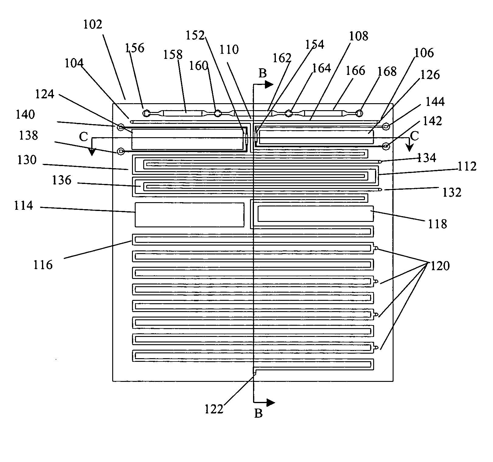
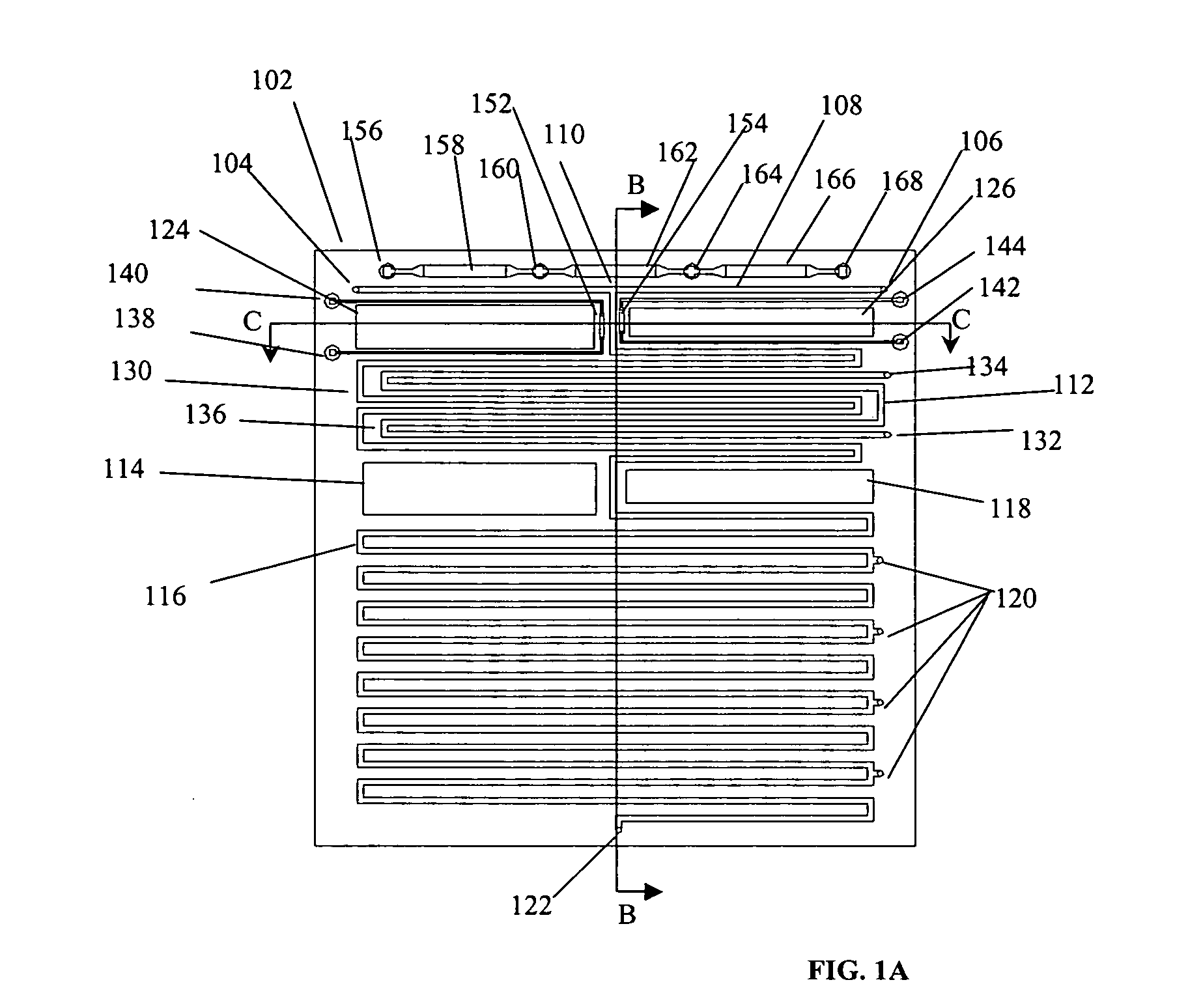
[0115] A module to nucleate and grow nanocrystals to the desired final size and size dispersion, incorporating reactant preconditioning, nucleation, reaction-induced thermal imbalance recovery, growth and growth termination sections, may be made on a single substrate.

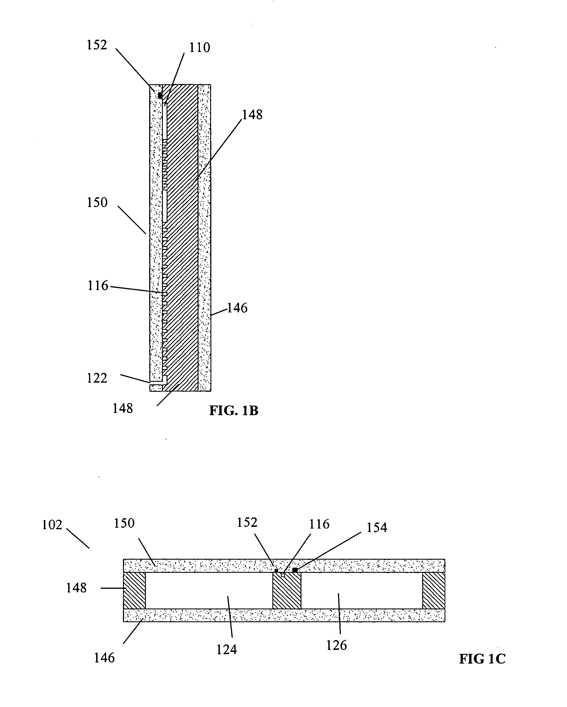
[0116] A (100) oriented, double side polished silicon wafer of a resistivity and conductivity type chosen for easy wafer bonding, and of sufficient diameter and thickness, is provided with a silicon dioxide layer on one side and a silicon nitride layer on the other. Silicon has a relatively high thermal conductivity, it is tolerant of chemicals and high and low temperatures and has many standard and well known coating and forming methods associated with it. The oxide side is patterned (“patterned” will be taken to mean photolithographically by means of standard photor...

example 2

[0123] This prophetic example illustrates the utilization of a microfluidic module incorporating appropriate sections for the purpose of making CdSe core nanocrystals with wet chemistry using a microfluidic module made by the process of example 1.

[0124] Prepare 1.0M trioctylphoshine selenide (TOPSe) by dissolving selenium pellets (99.99% purity, ˜2 mm pellet size, Aldrich Chemical Company) in trioctylphoshphine (TOP, tech grade quality or better, density=0.831 g / mL, Aldrich Chemical Company). Leave until a single-phase homogeneous solution is obtained. For the method in which two input reagents are employed, two separate constant volume pumps are used, in this case, two syringe pumps. In a glove box or using standard Schlenk line techniques, syringe 1 is charged with a sufficient mass of dry trioctylphosphine oxide (TOPO), heated above 55° C. (melting point, 50-54° C., tech grade quality or better, Aldrich Chemical Company). In a glove box, or using standard Schlenk line techniques...

example 3

[0134] This prophetic example illustrates the fabrication of a microfluidic module for the purpose of purifying, or separating nanocrystals from their first containing fluid reagent, and replacement of the first fluid reagent with a second fluid reagent, using wet chemistry. It would be advantageous to have one or more modules to purify nanocrystals without exposing the nanocrystals to air or using batch methods such as staged centrifuging.

[0135] The purification may be performed in a dedicated detachable module or the function can be integrated into a module that includes other functions such as growth and growth terminaton. The same method of manufacture can be used for a ligand-exchange section or module. A first silicon wafer is chosen with polishing and pin-hole free silicon nitride on both sides. The wafer doping and type is chosen consistent both with the anodic etching of desired pore sizes in the range of 100 nm to 10 μm and also to allow anodic wafer bonding.

[0136] The f...


PUM

PropertyMeasurementUnit
sizesaaaaaaaaaa
sizesaaaaaaaaaa
FWHMaaaaaaaaaa

Abstract

The present invention discloses microfluidic modules for making nanocrystalline materials in a continuous flow process. The microfluidic modules include one or more flow path with mixing structures and one or more controlled heat exchangers to process the nanocrystalline materials and reagents in the flow path. The microfluidic modules can be interconnected to form microfluidic reactors that incorporate one or more process functions such as nucleation, growth, and purification.

Description

CROSS REFERENCE TO RELATED APPLICATIONS [0001] This application claims the benefit and priority U.S. Provisional Application Ser. No. 60 / 449,590 filed Feb. 26, 2003 the contents of which are incorporated herein by reference in their entirety.BACKGROUND AND SUMMARY [0002] There has been much interest in the development and use of nanoparticles, which are sometimes also referred to as “quantum dots”. These very small, specially composed particles have a wide variety of applications in biological and other sciences. For example, semiconductor crystal nanoparticles (“nanocrystals”) can be fluorescent, providing very sensitive luminescent reporters of biological states and processes. Such nanocrystals have also been modified to impart properties for water solubility in order to take advantage of the many biological, biochemical and industrial applications. Exemplary nanoparticle sizes may range for example from about 1 nm to 500 nm in each dimension, but preferably from 1 nm to 200 nm in...

Claims


Application Information

Patent Timeline
Patent Type & Authority Applications(United States)
IPC IPC(8): B01F5/04B01F5/06B01F13/00B01JB01J19/00B01L3/00C30B7/00C30B29/60
CPCB01F5/0475C30B29/605B01F5/061B01F5/064B01F5/0641B01F5/0646B01F5/065B01F13/0059B01F13/0066B01F13/0079B01J19/0093B01J2219/00783B01J2219/00828B01J2219/00831B01J2219/00837B01J2219/0086B01J2219/00873B01J2219/00889B01J2219/00907B01J2219/00932B01J2219/00936B01J2219/00943B01J2219/00945B01J2219/0095B01J2219/00952B01J2219/00959B01J2219/00961B01J2219/00963B01J2219/00966B01J2219/00972B01J2219/00977B01L3/06B01L3/5027B01L3/502753B01L7/00B01L2200/147B01L2300/044B01L2300/0654B01L2300/0816B01L2300/0864B01L2300/0867B01L2300/0887B01L2300/0896B01L2300/1805B82Y30/00C30B7/00B01F5/0476B01F25/31421B01F25/3142B01F25/431B01F25/4321B01F25/432B01F25/4333B01F25/433B01F33/3012B01F33/3033B01F33/30
Inventor SWINEHART, PHILIP R.POLLARD, KIMBERLYMCGEE, CHRISTOPHERDHARMATILLEKE, SAMAN
Owner LAKE SHORE CRYOTRONICS INC
Why Eureka
Try Eureka