Method for storing and delivering hydrogen to fuel cells

a fuel cell and hydrogen storage technology, applied in the direction of electrical generators, sustainable buildings, mechanical equipment, etc., can solve the problems of high cost, unsafe, unportable, etc., and achieve the effect of reducing the tensile strength of the shell, effective release of hydrogen gas, and high tensile strength

Inactive Publication Date: 2006-02-09
JANG BOR Z
View PDF22 Cites 30 Cited by
  • Summary
  • Abstract
  • Description
  • Claims
  • Application Information

AI Technical Summary

Benefits of technology

[0017] The present invention provides a hydrogen gas storage and supply method, which includes two essential steps: (a) providing a chamber and a plurality of shell-core micro-spheres, each comprising a shell and a hollow or porous core, filled with pressurized hydrogen gas at an internal pressure P with the chamber containing therein the micro-spheres and free spaces not occupied by the micro-spheres; and (b) heating the micro-spheres to a temperature T to reduce the shell tensile strength σt to an extent that a tensile stress σ experienced by a shell of the micro-spheres spheres meets the condition of a σ≧ασt, causing hydrogen to diffuse out of the micro-spheres to provide hydrogen fuel from the chamber to a hydrogen-consuming device, where the material-specific parameter α has a value between 0.3 and 0.7. The shell stress a scales with the internal hydrogen gas pressure P and the tensile strength σt is a strong function of the micro-sphere temperature; σt decreasing with increasing temperature. This implies that for a highly pressurized micro-sphere (hence, a high tensile stress σ), it will take a lower temperature to effectively release the hydrogen gas.
[0018] The above condition was met, in the cases of using polymer micro-spheres to store hydrogen, when the temperature T was raised to be within the range of [Tg−25° C.] to [Tg+25° C.] for an amorphous or glassy polymer (Tg=glass transition temperature or softening point) or withing the range of [Tm−25° C.] to [Tm+10° C.] for a crystalline polymer (Tm=melting point). For glass micro-spheres, the condition was typically met when the temperature T was within the range of [Tg−50° C.] to [Tg+50° C.] for a glass with a glass transition temperature or softening point, Tg. For most of the organic polymers, the Tg or Tm is below 300° C. and more typically below 200° C. For conventional glasses, the Tg is typically higher than 500° C.; but for several classes of low-Tg glasses, the Tg is lower than 400° C. (some <300° C. or even <200° C.). We were able to produce hollow or porous core-shell micro-spheres from these glass materials and found it very advantageous to use these low-Tg micro-spheres to store hydrogen. Although low in Tg, these glasses have a sufficiently high tensile strength that make them capable of storing a great amount of hydrogen gas. Furthermore, the low Tg values mean low energy consumption and ease in reaching the critical temperature to release the hydrogen fuel.

Problems solved by technology

A major drawback in the utilization of hydrogen-based fuel cells for powering vehicles or microelectronic devices is the lack of an acceptable lightweight and safe hydrogen storage medium.
However, the containers for storing the liquefied hydrogen are made of very expensive super-insulating materials.
This is an economical and simple approach, but it is unsafe and not portable.
Compressed hydrogen gas in a large steel tank could be an explosion hazard.
The disadvantages of this approach are related to the low capacity and the cryogenic temperature required, which makes it necessary to use expensive super-insulated containers.
This renders the container for the metal hydride too heavy and expensive, and limits the practical exploitation of these systems for portable electronic and mobility applications.
However, there has been no independent confirmation of these unusually high figures.
The above review indicates that the hydrogen storage technology still has four major barriers to overcome: (1) low H2 storage capacity, (2) difficulty in storing and releasing H2 (normally requiring a high T to release and a high P to store), (3) high costs, and (4) potential explosion danger.
Such a heavy and complex system may not be very suitable for automotive and aerospace applications and is totally unfit for portable device applications (e.g., for use in fuel cells to power computers, cell phones, and other micro-electronic devices).
In either case, a significant amount of energy is consumed if glass micro-spheres, as suggested by Teitel, are used.
Both Tracy, et al. and Teitel did not suggest any convenient, easy-to-control, and less energy-intensive way to heat up the micro-spheres.

Method used


Image

  • Method for storing and delivering hydrogen to fuel cells
  • Method for storing and delivering hydrogen to fuel cells
  • Method for storing and delivering hydrogen to fuel cells

Examples


example 1

From Expandable Polystyrene Beads

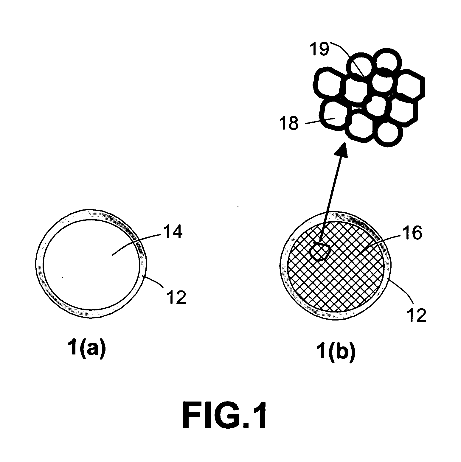
[0044] The production procedures for foamed plastics are adapted herein for the preparation of porous core-solid shell plastic beads. Micrometer-sized polystyrene (PS) beads were subjected to a helium gas pressure of approximately 7 atm and a temperature near 90° C. (inside a pressure chamber) for two hours, allowing helium gas molecules to diffuse into PS beads. The chamber was then cooled down to room temperature under a high helium gas pressure condition to seal in the gas molecules. These gas-filled beads were then placed in an oven preset at 110° C., allowing the supersaturated gas molecules to try to diffuse out and, thereby, producing micro-porous PS beads or “foamed” beads that have a thin solid skin. An optical microscopy study of several cross-sections of the shell structure of foamed plastic beads reveal bi-axial orientation of polymer chains, which were formed presumably due to the bi-axial tensile stress experience by the skin portion o...

example 2

Polymer Hollow Spheres

[0045] A 5-liter round bottomed flask was equipped with paddle stirrer, thermometer, nitrogen inlet and reflux condenser. To 2080 g of deionized water heated to 80° C. was added 5.5 g of sodium persulfate followed by 345 g of an acrylic polymer dispersion (40% solids) with an average particle size of 0.3 micron as the seed polymer. A monomer emulsion consisting of 55.5 g of butyl acrylate, 610.5 g of methyl methacrylate and 444 g of methacrylic acid in 406 g of water and 20 g of sodium dodecyl benzene sulfonate (23%) was added over a 2 hour period. This resulting alkali swellable core is used as the seed polymer for the following reaction:

[0046] To an identical 5-liter kettle (now empty) is added 675 g of water. After heating to 80° C., 1.7 g of sodium persulfate followed by 50.5 g (1 part by weight solids) of the above alkali swellable core is added. A monomer emulsion (9 parts by solids) consisting of 110 g of water, 0.275 g of sodium dodecylbenzene sulfona...

examples 3-a and 3-b

[0052] Two exemplary compositions are expressed in mole percent on the oxide basis as calculated from the batch, wherein BaO and ZnO additives were included in the base P2O5—Ag2O—X system, wherein X is selected from the group of Cl, Br, and I. The glasses were prepared in the following manner. Appropriate amounts of AgNO3 and H3PO4 were blended together and the mixture heated to about 200° C., at which time the AgNO3 melted and a clear, colorless, homogeneous solution resulted. Upon further heating, (e.g., up to 500° C.), water and nitrogen oxide fumes were evolved. The resulting melt was heated to about 700° C. and held at that temperature for about one hour to insure removal of water and the nitrogen oxides. A AgPO3 glass was formed by pouring the melt onto a stainless steel block. The glass was annealed at 160° C. An appropriate amount of a silver halide was then mixed with a comminuted sample of the AgPO3 glass and the mixture fused at about 450° C. The additives were then disso...


PUM

PropertyMeasurementUnit
Tmaaaaaaaaaa
diameteraaaaaaaaaa
diameteraaaaaaaaaa

Abstract

A hydrogen gas storage and supply method including: (a) providing a chamber and, contained therein, a plurality of shell-core micro-spheres, each comprising a shell and a hollow or porous core, filled with pressurized hydrogen gas at an internal pressure P; and (b) heating the micro-spheres to a temperature T to reduce the shell tensile strength σt to an extent that a tensile stress σ experienced by a shell of the micro-spheres meets the condition of σ≧ασt, causing hydrogen to diffuse out of the micro-spheres to provide hydrogen fuel from the chamber to a hydrogen-consuming device, where the material-specific parameter α has a value between 0.3 and 0.7. The shell stress scales with the internal hydrogen gas pressure and the tensile strength σt decreases with increasing micro-sphere temperature. For instance, this condition is met when the micro-spheres are heated to a temperature within the range of [Tg−25° C.] to [Tg+25° C.] for an amorphous polymer (Tg=glass transition temperature or softening point) or withing the range of [Tm−25° C.] to [Tm+10° C.] for a crystalline polymer (Tm=melting point). This method is useful for feeding hydrogen to a fuel cell used in a portable microelectronic device, automobile, and unmanned aerial vehicle where light weight is an important factor.

Description

FIELD OF THE INVENTION [0001] This invention relates to a hydrogen storage and supply method and more particularly to a method for safely storing and feeding hydrogen to a power-generating device such as a fuel cell or a hydrogen combustion engine. BACKGROUND OF THE INVENTION [0002] A major drawback in the utilization of hydrogen-based fuel cells for powering vehicles or microelectronic devices is the lack of an acceptable lightweight and safe hydrogen storage medium. Four conventional approaches to hydrogen storage are currently in use: (a) liquid hydrogen, (b) compressed gas, (c) cryo-adsorption, and (d) metal hydride storage systems. A brief description of these existing approaches is given below: [0003] (a) The liquid hydrogen storage approach offers good solutions in terms of technology maturity and economy, for both mobile storage and large-volume storage systems with volumes ranging from 100 liters to 5000 m3. However, the containers for storing the liquefied hydrogen are mad...

Claims


Application Information

Patent Timeline
Patent Type & Authority Applications(United States)
IPC IPC(8): H01M8/06F17D1/04
CPCC01B3/0005C01B3/001C01B2203/066H01M8/04208H01M8/0606Y02T90/32H01M2250/30Y02E60/324Y02E60/50Y02B90/18H01M2250/20Y02B90/10Y02E60/32Y02T90/40
Inventor JANG, BOR Z.
Owner JANG BOR Z
Why Eureka
Try Eureka