

Method of Producing Metal Oxide Film
a metal oxide film and metal oxide technology, applied in the direction of final product manufacturing, liquid/solution decomposition chemical coating, sustainable manufacturing/processing, etc., can solve the problems of poor shape-following properties, difficult to form an even metal oxide film onto a structural part, and difficult to form a film onto a fine structural part. , to achieve the effect of improving the adhesive properties, and reducing the difficulty of production
- Summary
- Abstract
- Description
- Claims
- Application Information
AI Technical Summary
Benefits of technology
Problems solved by technology
Method used
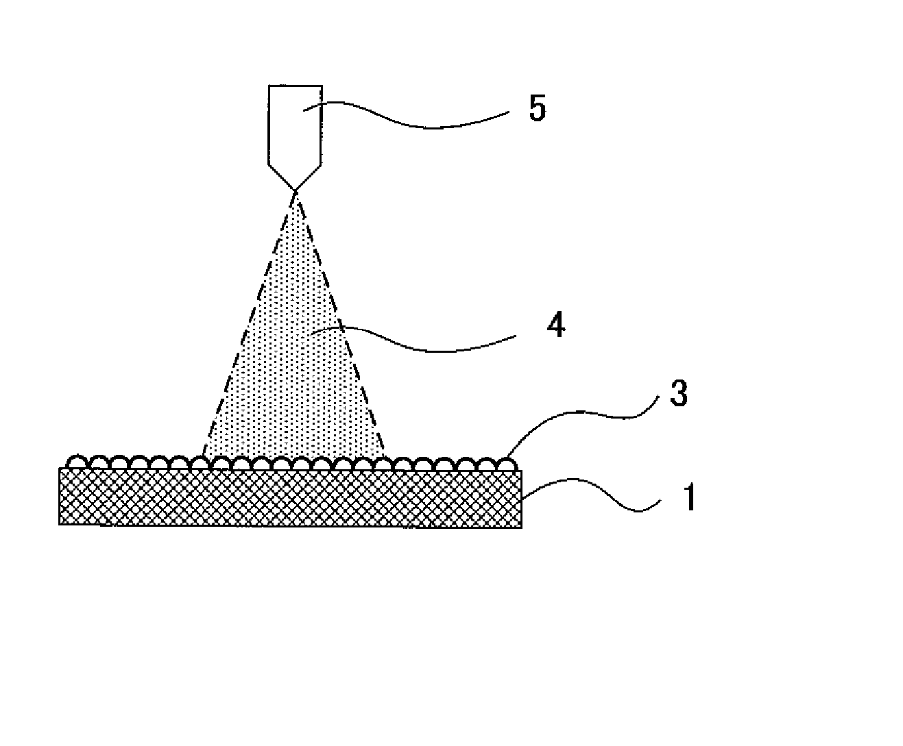
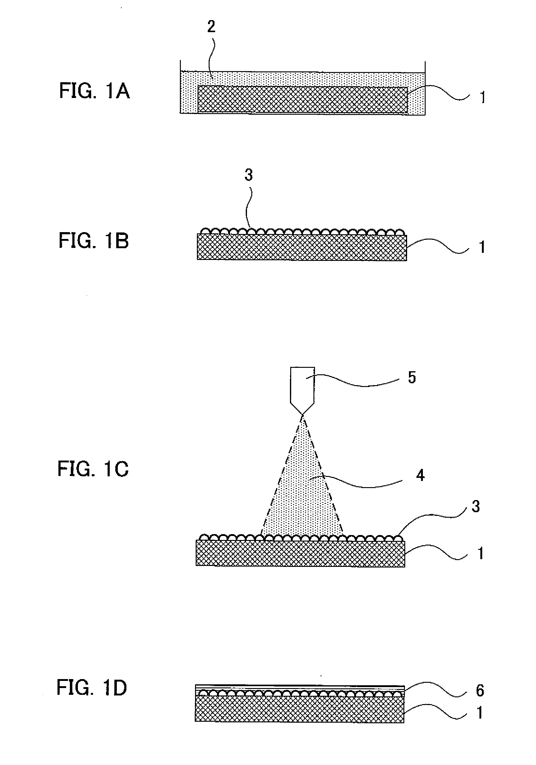
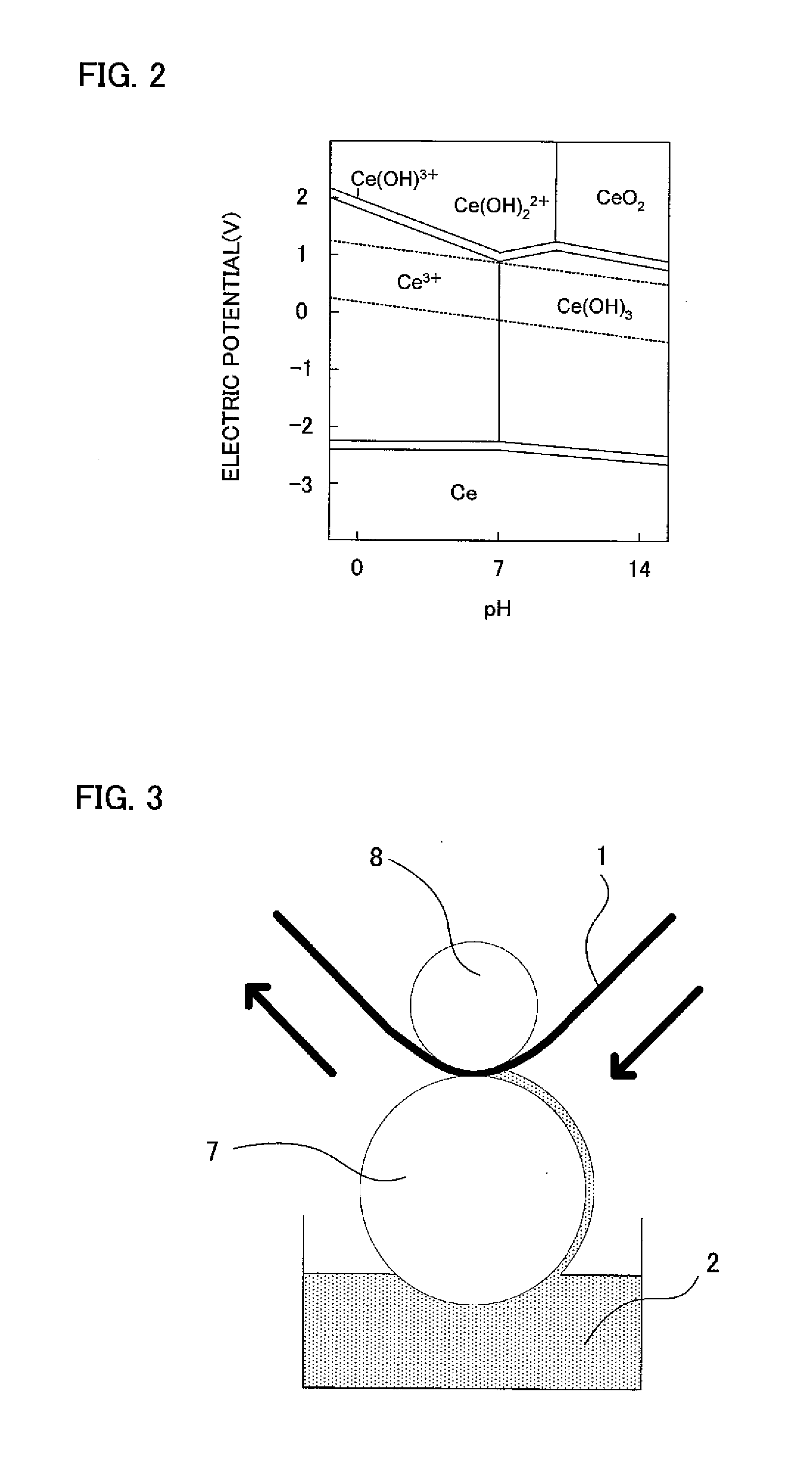
Image

Examples
example 1
Formation of a Zirconium Oxide Film on a SUS Substrate Subjected to Microfabrication
[0162] In the present example, a zirconium oxide film was formed on a SUS substrate subjected to a microfabrication to provide insulation properties.
[0163] In the example, a SUS304 (thickness: 1 mm) subjected to a microfabrication (grooves 100 μm in width, 10 mm in length, and 50 μm in depth) by an etching method was firstly prepared as a substrate.
[0164] Next, 5 g of a borane-trimethylamine complex (manufactured by KANTO KAGAKU) as a reducing agent was added to 1000 g of a 0.05 mol / L solution of oxyzirconium nitrate dehydrate (manufactured by KANTO KAGAKU) in water to yield a first metal oxide film forming-solution.
[0165] Next, the first metal oxide film-forming solution was heated up to a temperature of 80° C., and a Naflon Bubbler (manufactured by AS ONE CORPORATION) was used to generate air bubbles at a constant temperature of 80° C. At this time, the first metal oxide film-forming solution w...
example 2
Formation of a Zinc Oxide Film on a Copper Substrate Subjected to Microfabrication
[0171] In the present example, a zinc oxide film was formed on a copper substrate subjected to microfabrication to give corrosion resistance thereto while keeping the electroconductivity.
[0172] First, in the example, a copper (1 mm in thickness) subjected to microfabrication (grooves 50 μm in width, 10 mm in length, and 20 μm in depth) by an etching method was prepared as a substrate.
[0173] Next, a borane-dimethylamine complex (manufactured by KANTO KAGAKU) as a reducing agent was added to 1000 g of a 0.05 mol / L solution of zinc acetate (manufactured by KANTO KAGAKU) in ethanol, so as to give a concentration of 0.08 mol / L. Furthermore, thereto was added 1 g of potassium nitrite (manufactured by KANTO KAGAKU) as an auxiliary ion source to yield a first metal oxide film forming-solution.
[0174] Next, the first metal oxide film-forming solution was heated up to a temperature of 70° C., and a Naflon Bub...
example 3
Formation of an ITO Transparent Electrode Film on a Porous Substrate
[0182] In the present example, an even and dense ITO transparent electrode film was given to a porous-titanium-oxide-film-attached glass substrate.
[0183] First, to water and isopropyl alcohol as solvents were added titanium oxide fine particles having a primary particle diameter of 20 nm (P25, manufactured by Nippon Aerosil Co., Ltd.), acetylacetone, and polyethylene glycol (average molecular weight: 3000) to give concentrations of 37.5% by weight, 1.25% by weight, and 1.88% by weight, respectively. A homogenizer was used to produce a slurry where the above-mentioned sample was dissolved or dispersed. This slurry was coated on a glass substrate by a doctor blade method, the resultant was allowed to stand still for 20 minutes and dried at 100° C. for 30 minutes. Subsequently, the electric muffle furnace (P90, manufactured by Denken Co., Ltd.) was used to fire the substrate with the dried film at 500° C. under an at...
PUM
| Property | Measurement | Unit |
|---|---|---|
| temperature | aaaaa | aaaaa |
| thickness | aaaaa | aaaaa |
| thickness | aaaaa | aaaaa |
Abstract
Description
Claims
Application Information