
Optical film, and polarizing plate and liquid crystal display device using the optical film

a technology of optical film and polarizing plate, which is applied in the direction of polarizing elements, lighting and heating apparatus, instruments, etc., can solve the problems of disadvantageous separation of hardcoat layer and film, and achieve good antireflection ability, reduce deterioration, and prevent dimensional change

Active Publication Date: 2008-08-21
FUJIFILM CORP
View PDF8 Cites 29 Cited by
  • Summary
  • Abstract
  • Description
  • Claims
  • Application Information

AI Technical Summary

Benefits of technology

[0009]The present invention has been made to solve those various problems in conventional techniques and achieve the following aspects. That is, an aspect of the present invention is to provide an optical film reduced in the deterioration by an ultraviolet ray, assured of high antireflection ability, good prevention of dimensional change due to humidity, strong film property and no separation of layers during production or handling (e.g., coating, transportation), and excellent in the transparency and scratch resistance. Another aspect of the present invention is to provide an antireflection film excellent in the antireflection property and other optical performances as well as in the prevention of ultraviolet ray. A still another aspect of the present invention is to provide a high-quality polarizing plate and a high-grade liquid crystal display device each equipped with the above-described antireflection film.
[0010]As a result of intensive studies, the present inventors have found that when an ultraviolet-blocking layer and a hardcoat layer are sequentially stacked on a support comprising a polymer having an alicyclic structure and at least one member selected from a metal oxide fine particle and a polymer particle is contained as an ultraviolet absorbent, a well-balanced antireflection film satisfying both ultraviolet-blocking property and antireflection property can be obtained.

Problems solved by technology

However, the polymer film having an alicyclic structure and containing an ultraviolet absorbent exhibits poor adhesion to a hardcoat layer which is often stacked and used for enhancing the strength of the polarizing plate protective film, and the hardcoat layer is disadvantageously separated from the film.

Method used


Image

  • Optical film, and polarizing plate and liquid crystal display device using the optical film
  • Optical film, and polarizing plate and liquid crystal display device using the optical film
  • Optical film, and polarizing plate and liquid crystal display device using the optical film

Examples


synthesis example 1

Synthesis of Perfluoroolefin Copolymer (1)

[0321]In a stainless steel-made autoclave having an inner volume of 100 ml and equipped with a stirrer, 40 ml of ethyl acetate, 14.7 g of hydroxyethyl vinyl ether and 0.55 g of dilauroyl peroxide are charged, and the inside of the system is degassed and displaced with nitrogen gas. Furthermore, 25 g of hexafluoropropylene (HFP) is introduced into the autoclave, and the temperature is elevated to 65° C. The pressure when the temperature in the autoclave reaches 65° C. is 0.53 MPa. The reaction is continued for 8 hours while keeping this temperature and when the pressure reaches 0.31 MPa, the heating is stopped and the system is allowed to cool. At the time when the inner temperature drops to room temperature, the unreacted monomer is expelled and the autoclave is opened to take out the reaction solution. The obtained reaction solution is poured in a large excess of hexane and after removing the solvent by decantation, the precipitated polymer...

synthesis example 2

Synthesis of Ultraviolet-Absorbing Polymer Particle (J)

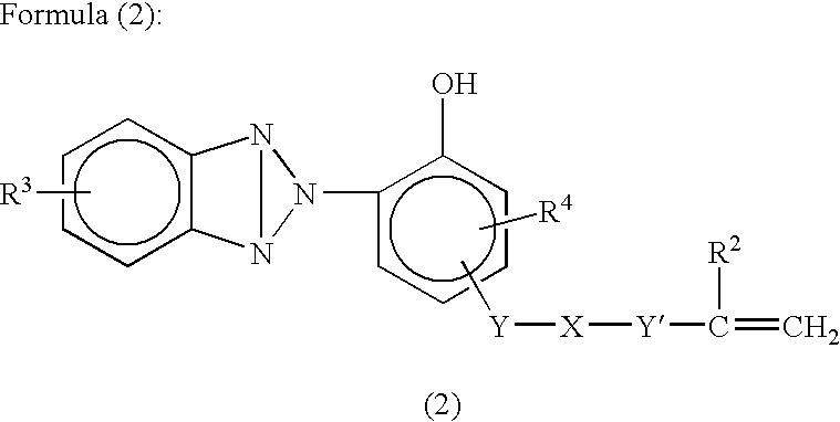
[0323]600 Parts of water is filled in a reaction vessel equipped with a stirrer and a reflux condenser, and 0.7 parts of polyvinyl alcohol and 2.7 parts of sodium dodecylbenzenesulfonate are added thereto and dissolved. Subsequently, a mixed solution containing 60.0 parts of an ultraviolet absorbing monomer 2-[2′-hydroxy-5′-(methacryloyloxy)ethylphenyl]-2H-benzotriazole {“RUVA-93”, trade name, produced by Otsuka Chemical Co., Ltd.}, 39.0 parts of methyl methacrylate, 1.0 part of ethylene glycol dimethacrylate and 2.0 parts of benzoyl peroxide is added thereto and stirred. This mixed solution is dispersed using a homogenizer at 9,000 rpm for 15 minutes and made uniform. The stirring is continued at 75° C. for 4 hours while blowing nitrogen gas. Thereafter, the product is lightly dehydrated by centrifugal separation, then washed with water and dried to produce Polymer Particle (J).

[Preparation of Coating Solution for Ultraviolet A...

formulation example 1-1

Preparation of Coating Solution (UV-A) for Ultraviolet Absorbing Layer

[0324]5.2 parts of sodium polyacrylate {“Poiz-530” (trade name), produced by Kao Corp.} as a dispersant, 10.5 parts of glycerin as an aggregation inhibitor and 49.3 parts of water are mixed with 5 parts of spindle-shaped fine particulate titanium oxide (TI-A) {average primary particle diameter of short axis diameter: 8 nm (short axis diameter at both ends of particle: 5 nm) and long axis diameter: 32 nm, aspect ratio: 4, rutile crystallinity: 55%}, and the mrxture is dispersed in “Dissolver” {manufactured by Tokushu Kika Kogyo Co., Ltd.} at 3,000 rpm for 30 minutes and then passed 5 times through a horizontal sand grinder at 2,500 rpm to obtain Dispersion (UV1).

[0325]Gelatin is mixed with Dispersion (UV1) such that the ratio of spindle-shaped fine particulate titanium oxide (TI-A) / gelatin in the coating solution (UV1) becomes 2 / 1. In this way, Coating Solution (UV-A) for Ultraviolet Absorbing Layer is prepared.


PUM

PropertyMeasurementUnit
Fractionaaaaaaaaaa
Thicknessaaaaaaaaaa
Thicknessaaaaaaaaaa

Abstract

An optical film includes a filmy support that includes a polymer having all alicyclic structure; an ultraviolet absorbing layer; and a hardcoat layer, wherein the ultraviolet absorbing layer has a beam transmittance of 5% or less in a wavelength region of 200 to 340 nm and includes at least one ultraviolet absorbent selected from the group consisting of a metal oxide fine particle and a polymer particle.

Description

BACKGROUND OF THE INVENTION[0001]1. Field of the Invention[0002]The present invention relates to an optical film, and a polarizing plate and a liquid crystal display device each using the optical film.[0003]2. Description of the Related Art[0004]With the remarkable progress in the information industry, a display device is utilized in various places. In particular, a liquid display device is making striking progress and is mounted in various instruments. In these liquid crystal display devices, stability of display quality in the installed environment is an important matter.[0005]The polarizing plate used in the liquid crystal display device is usually produced by sandwiching a polarizer between two protective films, and triacetyl cellulose (TAC) is preferably used as the polarizing plate protective film. However, humidity condition for a long time, sometimes causes a problem that light leakage or the like is generated and the display quality cannot be maintained.[0006]On the other h...

Claims


Application Information

Patent Timeline
IPC IPC(8): G02B5/22G02B1/10G02B5/30B32B7/02B32B27/18B82Y20/00B82Y30/00G02B1/11G02B1/111G02B1/14G02B1/16G02F1/1335
CPCG02B1/111G02F1/133528G02B5/3025G02B5/208
Inventor ASAKURA, TETSUYAHIROYUKI, YONEYAMAMATSUNAGA, NAOHIRO
Owner FUJIFILM CORP
Learn More