Apparatus and method for digital magnetic beads analysis

Active Publication Date: 2008-09-25
APPLIED BIOCODE
View PDF32 Cites 30 Cited by
  • Summary
  • Abstract
  • Description
  • Claims
  • Application Information

AI Technical Summary

Benefits of technology

[0023]In another aspect of the present invention, a microfluidic apparatus comprises a sheath flow system to provide steady and stable bead flow through the optical detection area. The sheath system includes one core flow, which carries the barcode beads, and two sheath flows, on the sides of or about or around the outer periphery of the core flow, pull the core flow into a proper dimension. The sheath flows, at much higher speed, can be pushed or pulled by vacuum, gravity, or pressure. By this method, the coded bead will align themselves in line and flow reliably, without wobbling or flipping, in the core flow channel through the detection zone. By adjusting the relative flow rate of core flow and sheath flows, the coded beads flow reliably in the flow system, thus it can be decoded and detected by an optical system accurately.
[0024]In another aspect of the present invention, the optical detection system consists of at least one illumination light source for barcode illumination and fluorescence detection. The wavelength of fluorescence excitation light source depends on the selection of the fluorophore.

Problems solved by technology

However, mechanical contact printing is not very attractive because it prints one spot per contact that results in relatively large printing variations from spot to spot or batch to batch, inconsistent spot morphology, misprinting, and slide surface variations, all of which are undesirable for DNA microarray analysis.
Further, distributing a small volume of liquid samples over a relatively large chip surface often encounters the problems of insufficient sample amounts or non-uniform distribution over the chip surface.
These problems can cause incomplete reactions or very long reaction time.
The problems of reflection configuration are (1) it is difficult to setup the collection optics in proper position, especially when the beads are in micrometer scale, and (2) the light collection efficiency is poor and the barcode contrast is low, especially when micro beads are in the micro flow system.
The fl

Method used


Image

  • Apparatus and method for digital magnetic beads analysis
  • Apparatus and method for digital magnetic beads analysis
  • Apparatus and method for digital magnetic beads analysis

Examples


Embodiment Construction

[0051]The present description is of the best presently contemplated mode of carrying out the invention. This description is made for the purpose of illustrating the general principles of the invention and should not be taken in a limiting sense. The scope of the invention is best determined by reference to the appended claims.

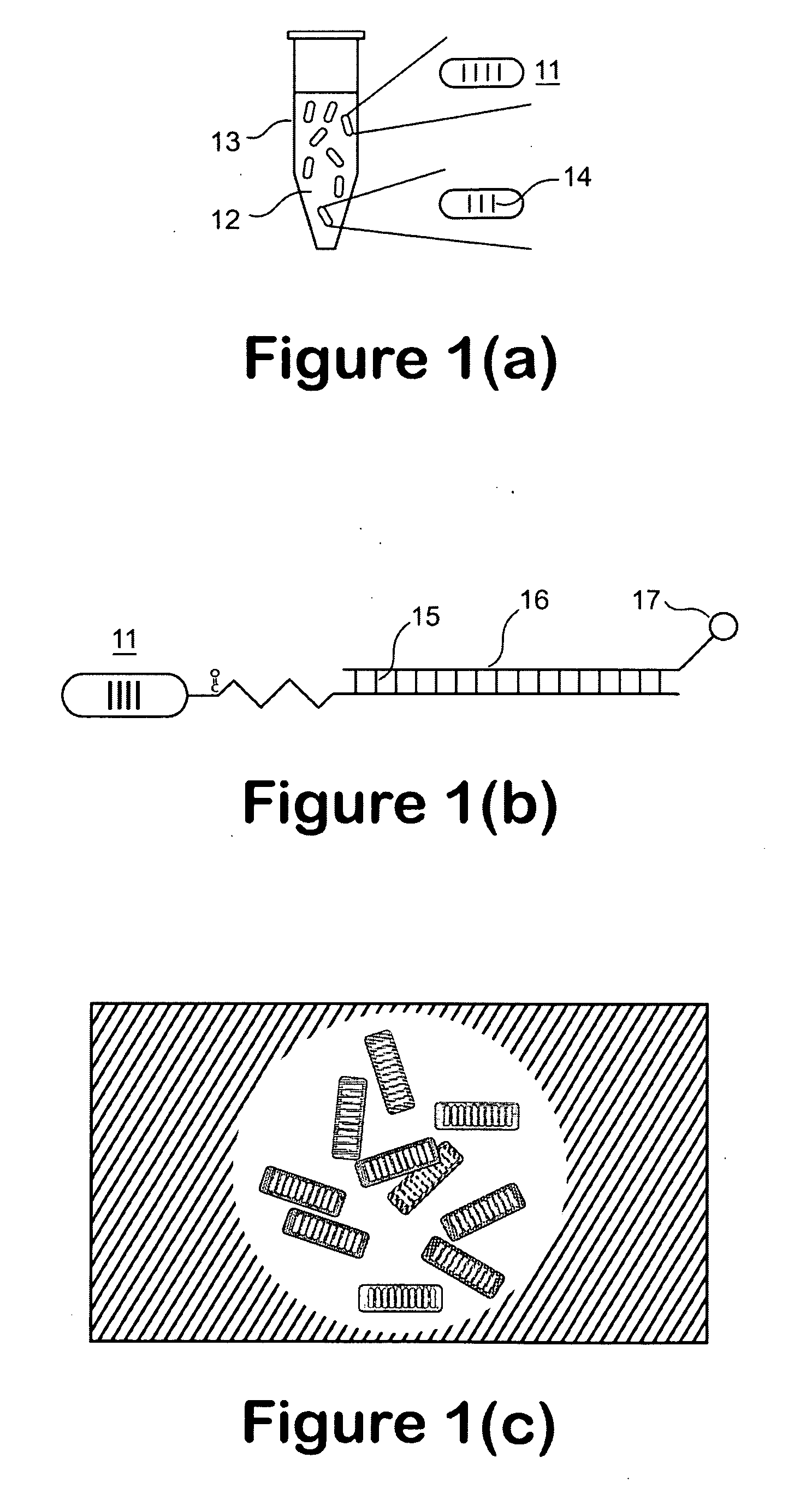
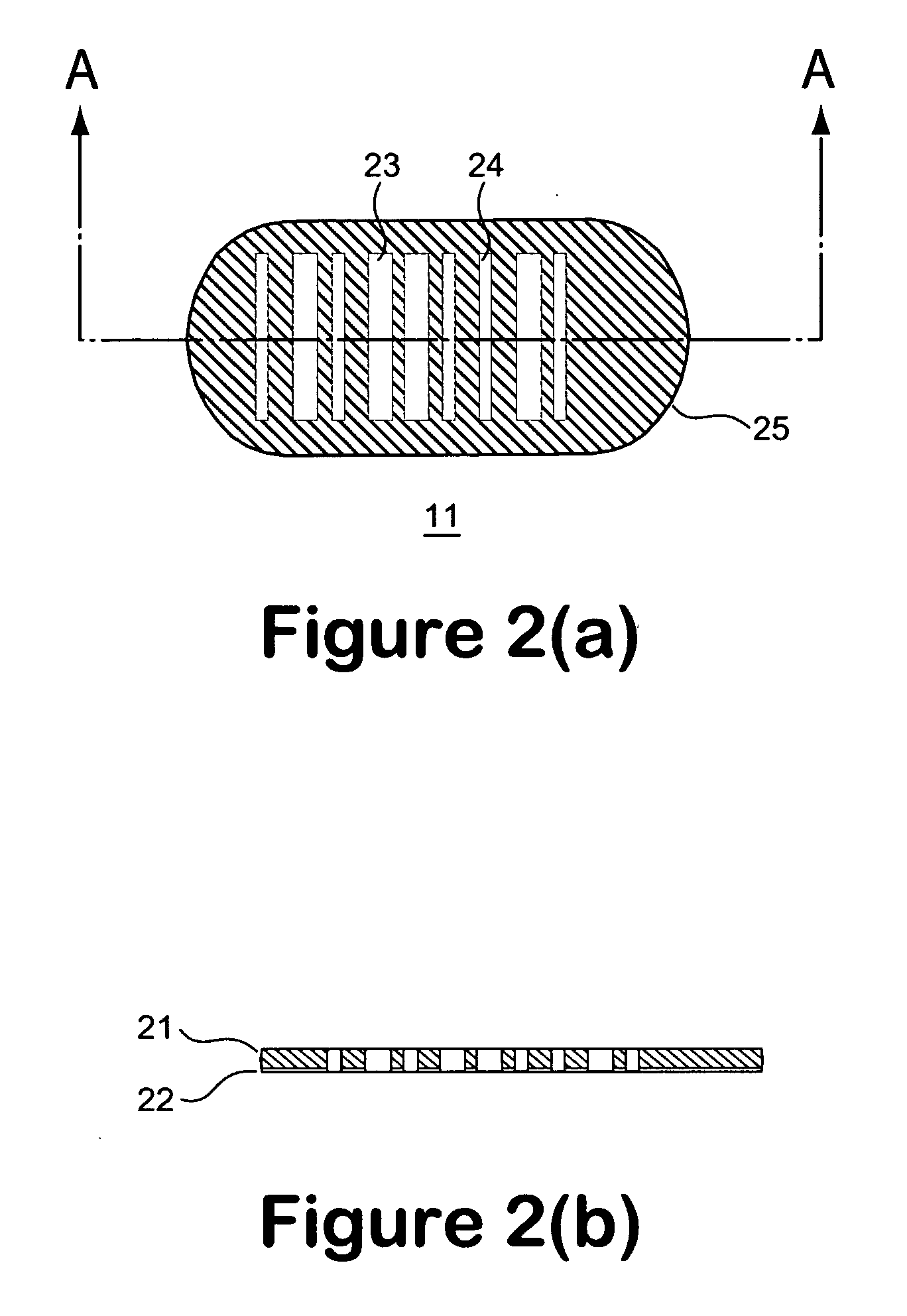
[0052]For purposes of illustrating the principles of the present invention and not by limitation, the present invention is described herein below by reference to a micro bead that is in the shape of a pallet, and by reference to bioanalysis. However, it is understood that the present invention is equally applicable to micro beads of other overall geometries, and which are applied for other applications requiring identification based on the identity of the beads, without departing from the scope and spirit of the present invention. To facilitate discussion below, the micro bead of the present invention is referred to as a LITAB, which stands for a light transmit...


PUM

PropertyMeasurementUnit
Lengthaaaaaaaaaa
Widthaaaaaaaaaa
Widthaaaaaaaaaa

Abstract

A micro bead having a digitally coded structure that is partially transmissive and opaque to light. The pattern of transmitted light is determined by to decode the bead. The coded bead may be structured a series of alternating light transmissive and opaque sections, with relative positions, widths and spacing resembling a 1D or 2D bar code image. To decode the image, the alternating transmissive and opaque sections of the body are scanned in analogous fashion to bar code scanning. The coded bead may be coated or immobilized with a capture or probe to effect a desired bioassay. The coded bead may include a paramagnetic material. A bioanalysis system conducts high throughput bioanalysis using the coded bead, including a reaction detection zone and a decoding zone. Alternative method for barcode determination is based on barcode pattern image processes. Microbeads can also be settled down to the bottom of the well in a microplate, so the barcode can be decoded by image processed directly. Therefore, multiple-analyte tests can be performed in one single well. Microplate is a standard format; each plate can have 96, 384, or 1536 patient samples. The bead image is taken with a conventional microscope and optical detector from the bottom of an optically clear microplate, and barcode pattern can be decoded by image software. Therefore, the whole bead experiment can be performed in the microplate without taking the beads out.

Description

[0001]This application is a continuation-in-part application of U.S. patent application Ser. No. 11 / 502,606, filed Aug. 9, 2006, and U.S. patent application Ser. No. 11 / 580,514, filed Oct. 13, 2006, which claims the benefit of the priority of Provisional Patent Application No. 60 / 706,896, which was filed Aug. 9, 2005 and Provisional Patent Application No. 60 / 964,108, which was filed Aug. 8, 2007. This provisional application is fully incorporated by reference, as if fully set forth herein. All other publications and U.S. patent applications disclosed herein below are also incorporated by reference, as if fully set forth herein.BACKGROUND OF THE INVENTION[0002]1. Field of the Invention[0003]The invention relates generally to assay beads and methods for use thereof to carry out multiplexed bioassays with digital magnetic beads, and more particularly multiplexed bioassays using micro-volume samples, such as protein and nucleic acid analysis.[0004]2. Description of Related Art[0005]As c...

Claims


Application Information

Patent Timeline
IPC IPC(8): C40B60/12
CPCC12Q1/6813C12Q1/6846G01N33/54326C12Q2563/107C12Q2563/155
Inventor HO, WINSTON Z.COLLINS, JOHN
Owner APPLIED BIOCODE
Why Eureka
Try Eureka