
Method for Testing the Integrity of Membranes

a filtration membrane and integrity technology, applied in the field of evaluating the integrity of filtration membranes, can solve the problems of preventing the full utilization of ultrafiltration (uf), microfiltration and nanofiltration technologies for water treatment, and accurately monitoring,

Inactive Publication Date: 2009-09-03
YISSUM RES DEV CO OF THE HEBREWUNIVERSITY OF JERUSALEM LTD +1
View PDF1 Cites 17 Cited by
  • Summary
  • Abstract
  • Description
  • Claims
  • Application Information

AI Technical Summary

Benefits of technology

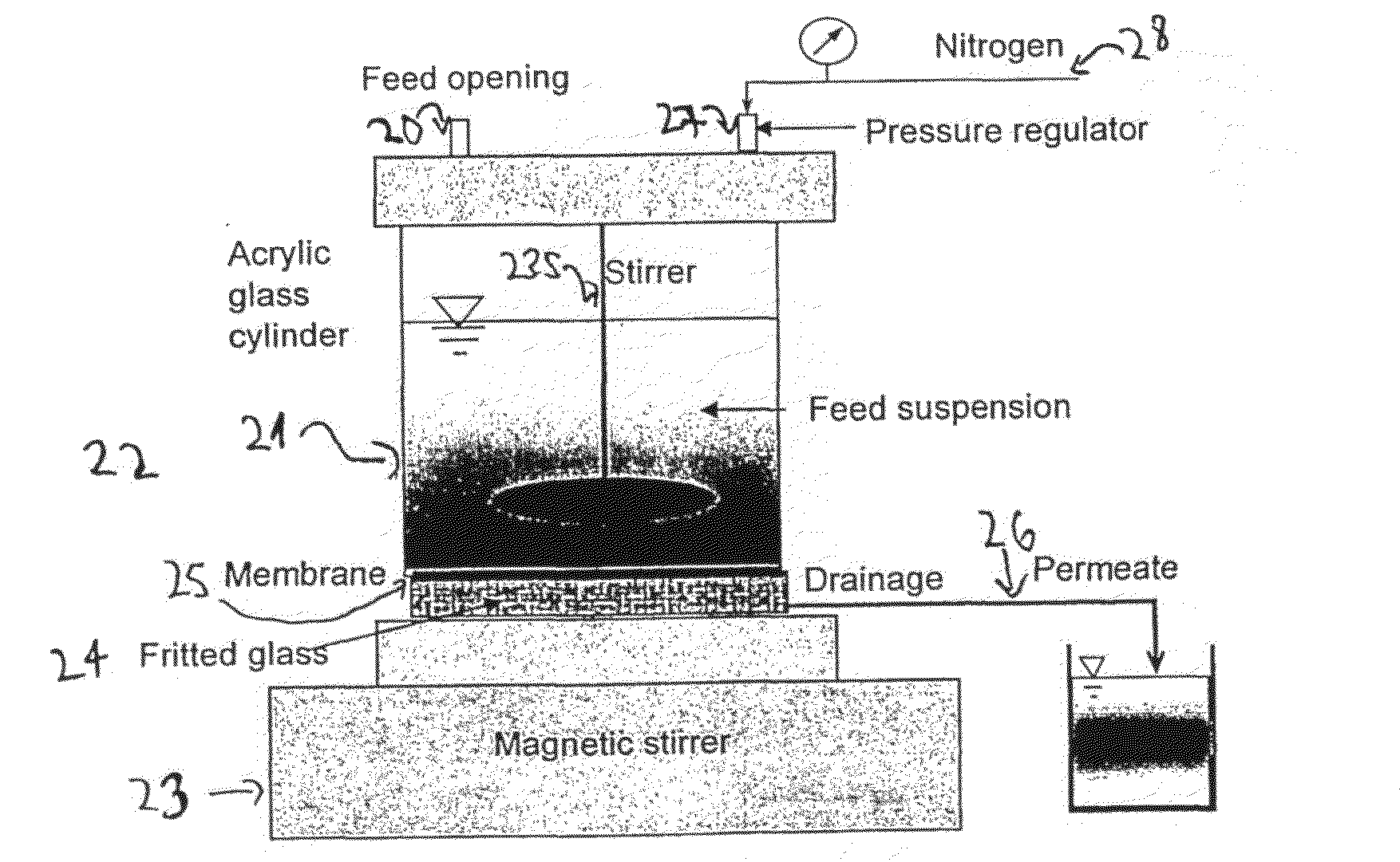
[0008]It has now been found that it is possible to accurately and consistently evaluate the integrity of a membrane by passing therethrough a population of nano-probes characterized by a high degree of monodispersivity and enhanced observability, collecting the permeate (i.e., the liquid that passes through the membrane) and testing the same for the presence of said nano-probes.
[0016]As pointed out hereinabove, an important property that is satisfied by nano-probes to be used according to the present invention is their enhanced observability. In order to facilitate a rapid quantification of the nano-probes in the permeate generated by the membrane and thus allow the detection of breaches in membranes under field conditions within a very short time, it is preferred to use nano-probes that can be readily observed in very low concentration.
[0032]The inventors have also found that it is possible to accurately and consistently evaluate the integrity of a membrane by passing therethrough gold nanoparticles (preferably after appropriate clean up to remove a large portion of the smaller particles), collecting the permeate and analyzing the same for the presence of said gold nano-particles by means of one or more electrochemical techniques.
[0035]The organic coating provided on the surface of the gold cores prevents the agglomeration of the nanoparticles in the aqueous medium, thus maintaining the stability of the colloidal system, such that a substantially uniform particle size distribution of said nanoparticles population is retained during a long storage period and over broad concentration and / or pH ranges. To this end, the organic coating preferably comprises ionizable functional groups, and more specifically, carboxylic groups (—COOH), which, when present in their corresponding ionized form, produce electrical repulsion forces between the individual nanoparticles in the aqueous suspension. Alternatively, it is possible to use organic coating composed of bulky, long-chains molecules capable of causing steric repulsion between the nano-particles. To this end, sulfur-containing compounds, and especially alkanethiols may be used, in view their ability to adhere onto the gold surface by means of forming strong Au—S bonds. Possible alkane thiol compounds include propylthiol, butylthiol, pentylthiol and other straight chain alkyl thiols.
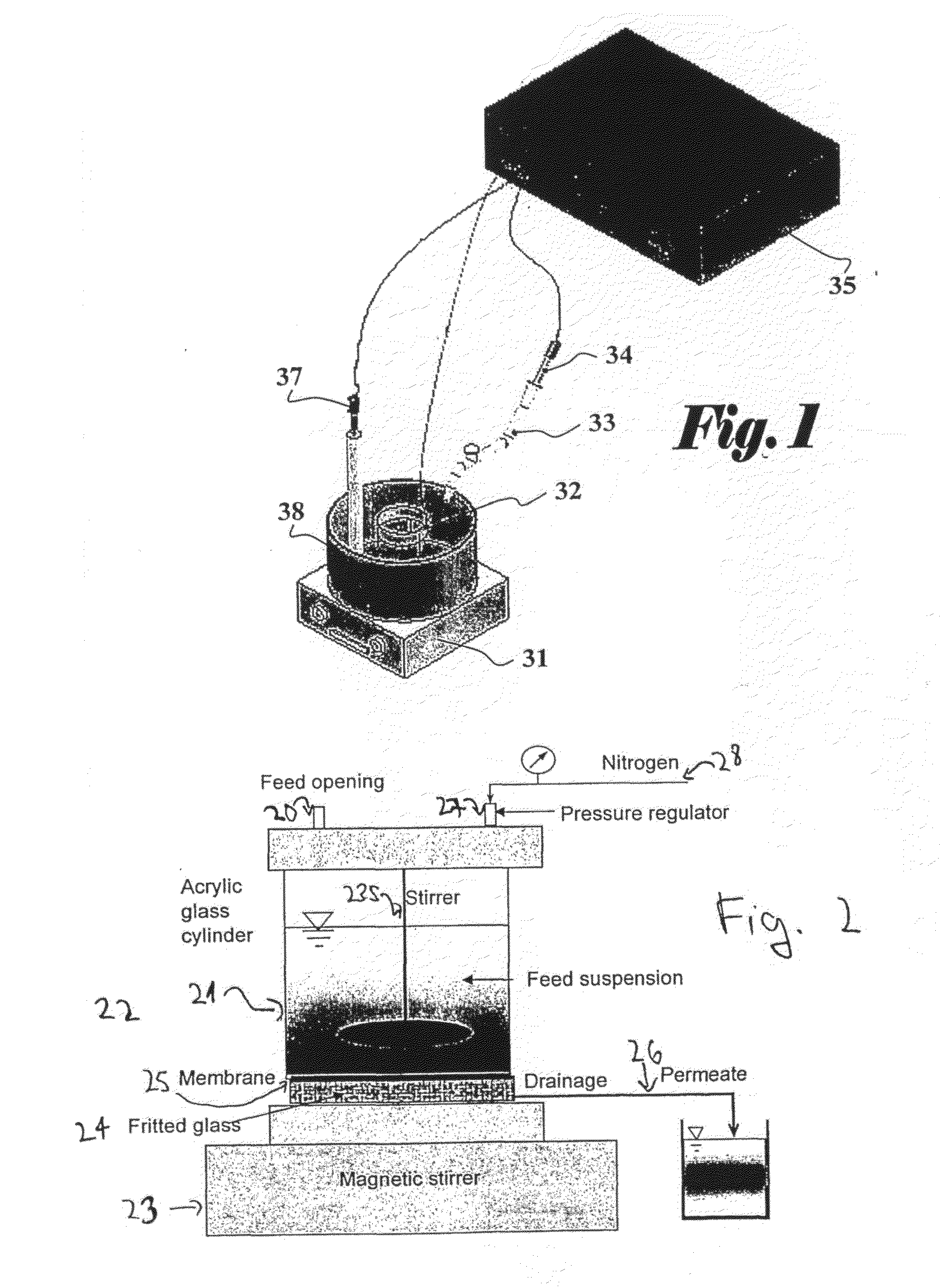
[0045]In operation, a volume (5-40 ml) of tested sample is placed in the sample holder and the working electrode assembly is initially connected in a cathodic mode to the power source. The cathodic potential is typically in the range of −0.4 V to −1.1 V, and more preferably at about −0.7 V. The electroplating of the electrode is preferably allowed to continue for 1 to 15 minutes. It has been found that the addition of mercury ions (Hg2+) at a concentration in the range of 50 to 200 ppm into the tested sample may considerably facilitate the analysis. The presence of mercury ions assist in the cathodic accumulation, allowing the deposition stage to be relatively rapidly accomplished. This advantage may be conveniently exploited without running the danger of interfering with the results, since in the subsequent stripping stage, as will be illustrated in the examples below, the characteristic voltage peaks assigned to mercury and gold are easily distinguishable.
[0053]In addition to the detection of changes in the integrity of ultrafiltration membranes in water treatment plants, the integrity test provided by the present invention may also be used by membrane manufacturers for tailoring a suitable and safe cleaning protocol (namely, cleaning agents and concentration thereof) for their membranes. As will be shown in the examples below, in tests carried out using these probes breaches in membrane were detected as early as the first appearance of small holes with an average diameter of 30 nm. It should be noted that the use of the sensitive probes of the invention enables the detection of an early breach at C•t (concentration of cleaning solution×contact time) levels of 5 g / L-h following chemically treating the membrane with cleaning (oxidizing) agents. This C•t level is three times lower than the breach detection accomplished by the conventional bubble point method, which detected breaches only after application of an oxidizing agent at a C•t level of 18 g / L-h. In order to detect a breach at such a C•t level (5 g / L-h) with the bubble point method, it will require the application of additional pressure of 10 bars, which is four times greater than the maximum pressure permitted by membrane manufacturers.

Problems solved by technology

However, the lack of means to accurately monitor membrane integrity over long-term operation is preventing the full exploitation of the potential of ultrafiltration (UF), microfiltration and nanofiltration technologies for water treatment.
Membrane integrity, i.e., the absence of feed leakage through affected or broken membranes, or passage through seals, can be compromised as a result of factory defects, improper shipping and maintenance, faulty integrity tests, excessive exposure to chemicals during chemical clean-up or natural wear under continuous operation.
Furthermore, the PDT and the DAF tests may at times cause membrane breakage during the test and may yield false-positive results due to the membrane being partially unwetted (after backwash) or due to seasonal viscosity changes (EPA, Membrane Filtration Guidance Manual, U.S. Environmental Protection Agency Office of Water (4601), EPA 815-d-03-008, June 2003).
These tests also suffer from subjective interpretation of pressure deterioration.
Thus, plants that rely on pressure integrity tests alone are likely to continue their operation beyond the point where their membrane integrity has been compromised.

Method used


Image

  • Method for Testing the Integrity of Membranes
  • Method for Testing the Integrity of Membranes
  • Method for Testing the Integrity of Membranes

Examples


example 1

Testing the Integrity of Intact Membranes by Means of MS2 Bacteriophages

Preparation

[0070]The initial stock of MS2 bacteriophages (DSM-No 13767) along with Escherichia coli host cells (DSM-No 5695) were purchased from German Collection of Microorganisms and Cell Cultures (DSMZ, Braunschweig, Germany). The bacteriophages were prepared by inoculation of 1:1 ratio of phages and host cells to the overlayer. After 24 hours incubation at 37° C., the overlayer containing the infected bacterial cells was scrapped into 50-ml tubes. Purification of the bacteriophage culture was accomplished by chloroform extraction. The stock was enumerated by plaque-assay method using the double-layer technique.

[0071]The initial titer was diluted to the concentration of 2×10¹¹ PFU / ml and labeled with fluorescein-5-isothiocyanate, FITC, fluorescein, 5-(4,6-dichlorotriazinyl)aminofluorescein, 5-DTAF, or rhodamine B. For FITC and DTAF, 1.2 mL of MS2 phages in 0.1 M borate buffer, pH 9.2, were mixed with 0.021 g ...

example 2

Testing the Integrity of Intact Membranes by Means of T4 Bacteriophages

2A: Fluorescent Dye Labeling of T4 Bacteriophages

Preparation

[0074]Five ml of an initial solution containing 1010 (ten to the power of ten) T4 phages were washed by introducing them into a dialysis membrane bag, and then they were left overnight in one liter of 10 mM of HEPES buffer at 4° C., to give Solution A. Into 5 ml of Solution A were added 25 mg of commercial Sulfo-N-hydroxysuccinimidobiotine (EZ-link Sulfo-NHS-Biotin of Pierce, Rockford, Ill. USA) and the mixture was left to react for 24 hours at 4° C., to give Solution B.

[0075]250 microliter of solution B were mixed with 500 microliter of streptavidin-fluorescein conjugate (commercially available, from Amersham Biosciences UK limited, Amersham Place, Little Chalfont Buckinghamshire, England. Catalogue number RPN1232-2ML) and the resulting solution was left to react for 24 hours at 4° C. The obtained solution was washed for two days by introducing it into ...

example 3

Testing the Integrity of Intact Membranes by Means of Proteins

Preparation

[0091]Bovine serum albumin (cold alcohol precipitated BSA) was purchased from Sigma-Aldrich. Israel Ltd. (Rehovot, Israel). A 0.15-g sample was dissolved in 500 ml deionized water (RO quality) to form a 0.3 g / L protein solution. The solution was labeled with fluorescein-5-isothiocyanate, FITC, fluorescein, 5-(4,6-dichlorotriazinyl)aminofluorescein, 5-DTAF, or rhodamine B. Same procedure as in working Example 1 was used. The labeled protein mixture was purified by membrane dialysis (The Scientific Instrument Center Ltd., London, UK) under stirring.

The Test

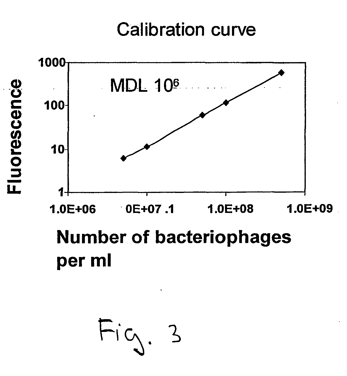
[0092]Fifty ml of the obtained stock was withdrew from the storage and filtered through the membrane. Ten ml of the permeate were collected and analyzed with Perkin-Elmer LS-50B FL fluorescence spectrometer (Perkin Elmer, Norwalk, USA) equipped with a 1-cm optical path length cuvette. The obtained intensity of the sample was compared to the calibration curve ob...


PUM

PropertyMeasurementUnit
size distributionaaaaaaaaaa
diameteraaaaaaaaaa

Abstract

A method for evaluating the integrity of microfiltration, ultrafiltration and nanofiltration membranes, which method comprises passing a liquid that contains a substantially mono-dispersed population of nano-probes through said membrane to form a permeate and testing said permeate for the presence of said nano-probes, wherein the non-detection of said nano-probes in said permeate indicates that said membrane is substantially intact.

Description

FIELD OF THE INVENTION[0001]The present invention concerns methods for evaluating the integrity of filtration membranes by the use of probes.BACKGROUND OF THE INVENTION[0002]Membrane systems are being increasingly used for the direct treatment of drinking water. However, the lack of means to accurately monitor membrane integrity over long-term operation is preventing the full exploitation of the potential of ultrafiltration (UF), microfiltration and nanofiltration technologies for water treatment. Membrane integrity, i.e., the absence of feed leakage through affected or broken membranes, or passage through seals, can be compromised as a result of factory defects, improper shipping and maintenance, faulty integrity tests, excessive exposure to chemicals during chemical clean-up or natural wear under continuous operation.[0003]Several direct and indirect integrity tests for detection of system breaches are currently in use.[0004]The direct integrity testing methods include the acousti...

Claims


Application Information

Patent Timeline
Patent Type & Authority Applications(United States)
IPC IPC(8): C12Q1/70C12N7/00
CPCB01D65/102
Inventor LEV, OVADIAGUN, GENIAGITIS, VITALY
Owner YISSUM RES DEV CO OF THE HEBREWUNIVERSITY OF JERUSALEM LTD
Learn More