System, method and device for tissue-based diagnosis

a tissue-based diagnosis and system technology, applied in the field of tissue-based diagnosis, can solve the problems of increasing misdiagnosis and inappropriate use, unable to explain current methods also fall short of explaining the complete molecular genesis of diseases, so as to facilitate the passage of drugs, and improve the effect of tissue flux

Inactive Publication Date: 2011-09-01
RGT UNIV OF CALIFORNIA
View PDF37 Cites 43 Cited by
  • Summary
  • Abstract
  • Description
  • Claims
  • Application Information

AI Technical Summary

Benefits of technology

[0023]Another object of the current invention is to provide a method and device for liquefying a tissue of a subject for facilitating the passage of a drug across or into the tissue. The method and device disclosed above are applicable not only to collection of tissue constituents but also to drug delivery. The device and method involve applying energy and a liquefaction medium to a tissue of interest of a subject, and delivering a drug through or into the site of the tissue to be liquefied. The advantage of using the present invention is 1) to provide higher fluxes of drugs into a tissue, and 2) to allow greater control of fluxes into a tissue. Drugs which would simply not pass through the tiss

Problems solved by technology

However, this information is not currently used in diagnostic methods due to a lack of patient-friendly and standardized methods for routine sample collection from tissues.
Instead, clinical diagnosis is invariably performed by visual observation and histopathological analysis of tissue biopsies, which are highly limited due to their qualitative nature, leading to increased misdiagnosis and inappropriate use.
In additio

Method used


Image

  • System, method and device for tissue-based diagnosis
  • System, method and device for tissue-based diagnosis
  • System, method and device for tissue-based diagnosis

Examples


example 1

Sampling of Skin by an Abrasive Energy-Based Device

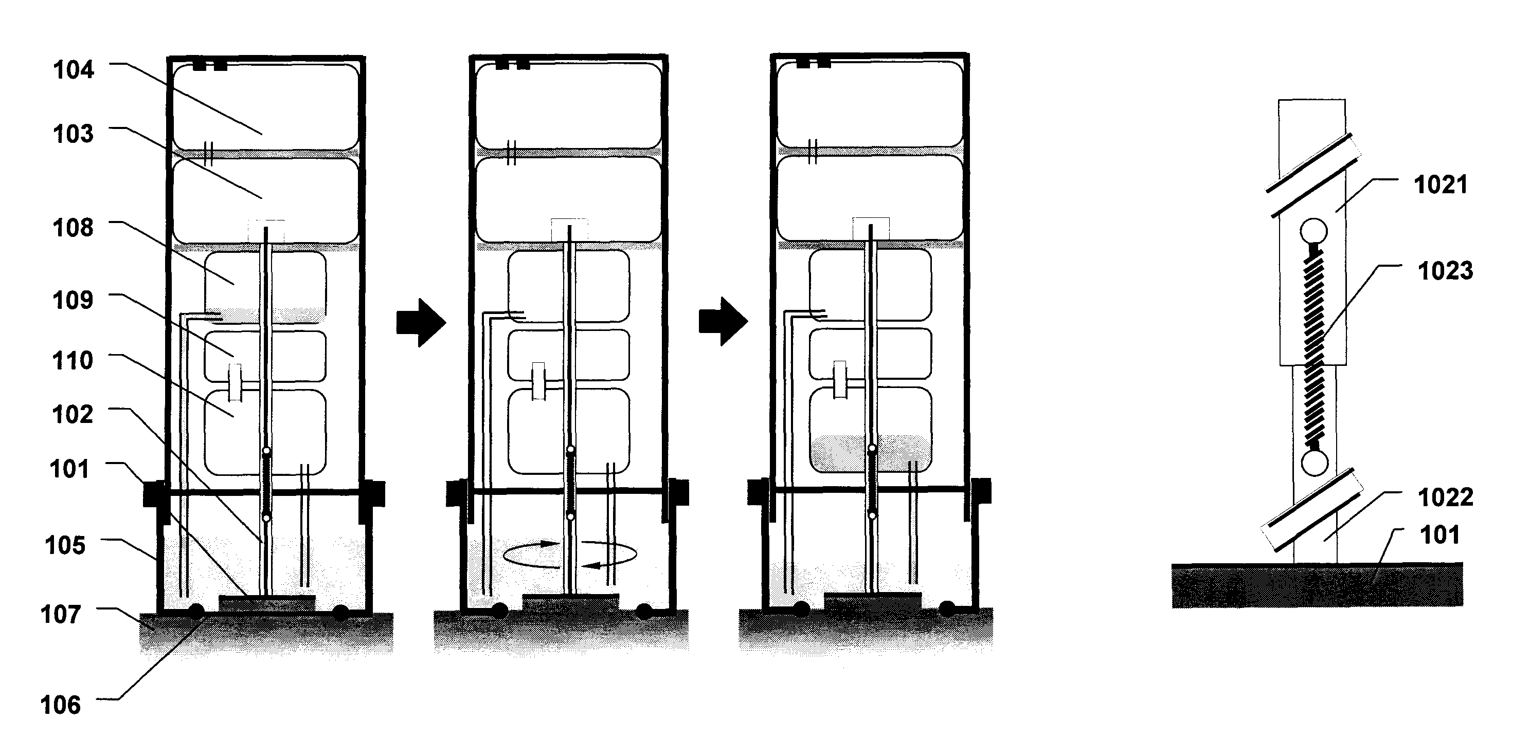
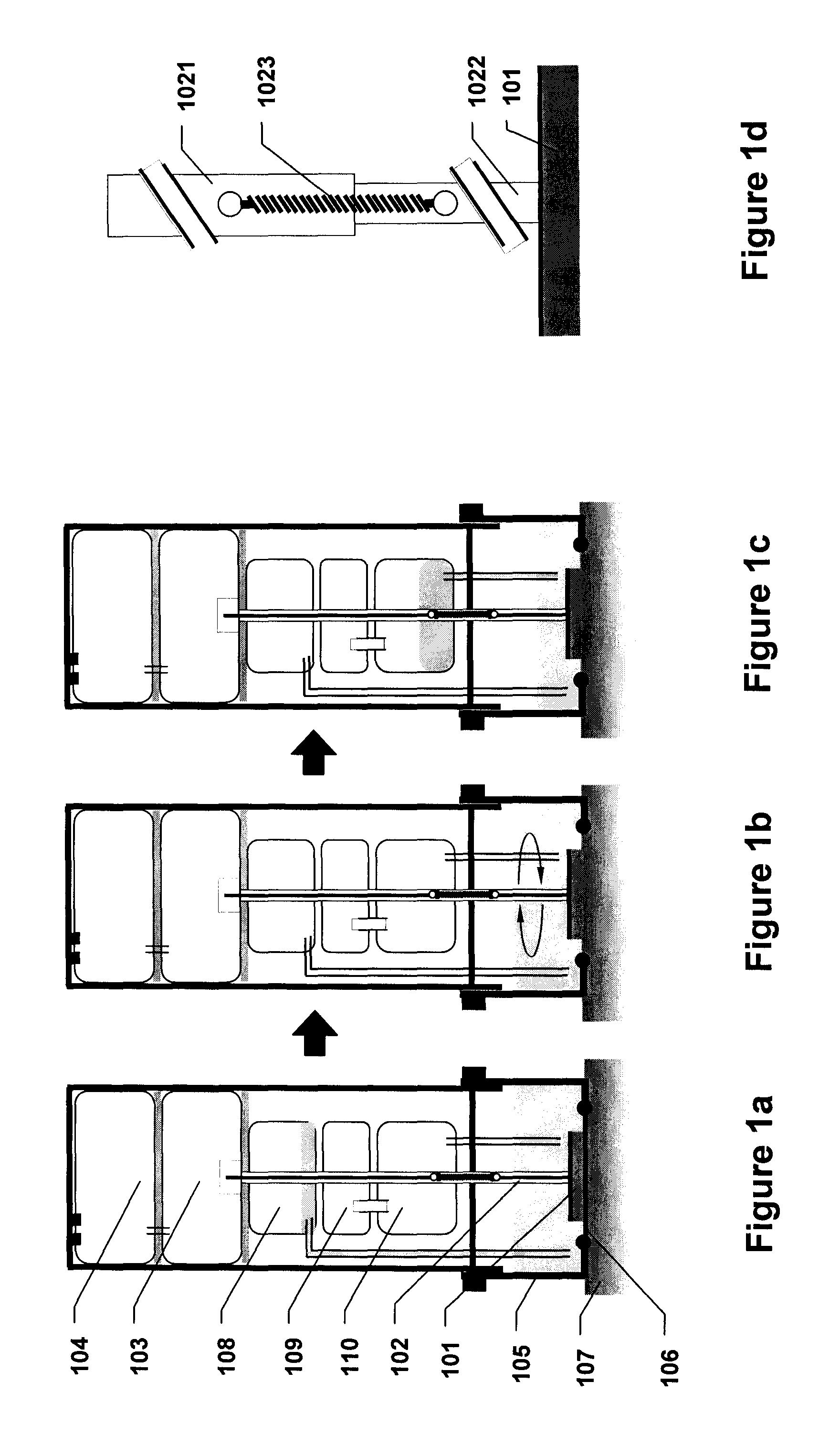
[0183]Referring to FIGS. 7a through 7e, an abrasive energy-based tissue liquefaction device for sampling of skin tissue is described. Device is assembled from three components—751 (assembly of device housing 701 containing motor 704 and electrical conductivity components 705 and 706); 752 (disposable assembly of LPM cartridge 708, collection container 707 and needle 709); and 753 (disposable assembly of LPM housing 712, abrasive pad 711 and shaft 710) (FIG. 7a). The assembled device is placed against a pre-identified region of interest on skin 713, such that abrasive pad 711 is facing skin 713 (FIG. 7b). Sliding plunger 702 located on top of the device is pushed towards skin, which pushes needle 709 into LPM cartridge 708, breaking its sterile seal and transfers LPM into housing 712. Sliding plunger 702 also energizes motor 704 through battery pack 703, setting the shaft 710 and abrasive pad 711 in rotary motion against skin tissue ...

example 2

Sampling of Skin by a Microneedle-Based Device

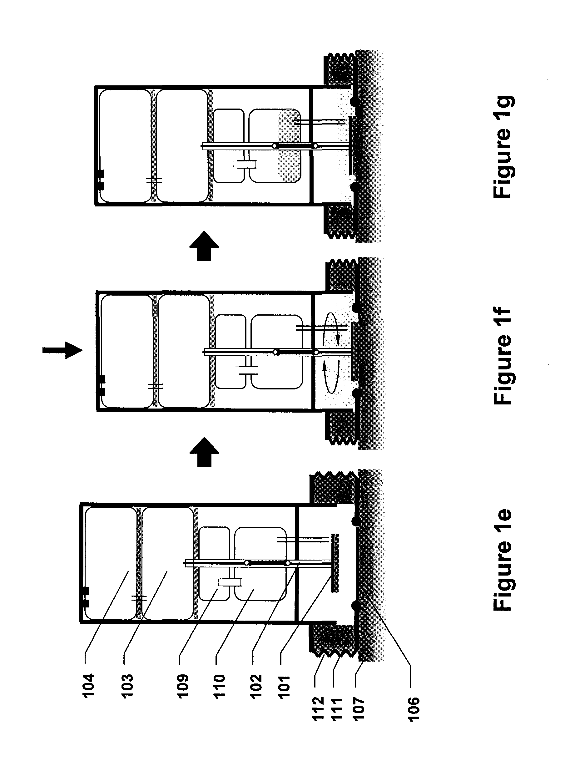
[0184]Referring to FIGS. 8a through 8d, a microneedle-based tissue liquefaction device for sampling of skin tissue is described. The device is placed against a pre-identified region of interest on skin 807, such that microneedle bearing patch 805 is facing skin 807 (FIG. 8a). Sliding plunger 801 located on top of the device is pushed towards skin 807 such that LPM soaked sponge 804 is squeezed and releases LPM into housing 803 (FIG. 8b). Consequently, microneedles in patch 805 and housing 803 at the skin interface are filled with LPM. To initiate liquefaction process, sliding plunger 801 is further pushed into skin tissue 807 leading to insertion of microneedles 805 into skin tissue 807 (FIG. 8c). As skin tissue is liquefied, tissue components are dissolved in LPM contained in housing 803. Upon completion of skin liquefaction, pre-vacuumized sample container 802 is pushed towards skin tissue 807 such that needle 806 punctures sample cont...

example 3

Reservoir Housing for Capturing Tissue Analytes

[0185]Referring to FIG. 9 (Panels a-d) a design for a reservoir housing to capture tissue analytes from liquefied tissue samples is described. The reservoir housing (901) is intended to be used with energy-application devices described herein, as a container to collect the liquefied tissue sample. The housing is coated with capture substrates (902) which selectively bind to tissue analytes (903) present in the sample. Upon sufficient incubation of the tissue sample, the sample is discarded while the analytes (903) are held in the housing. The analytes are eluted by an elution buffer in the housing for subsequent capture of the analytes as a separate sample (904). Alternatively, the housing can be integrated in an analytical tool for analyzing the bound analytes (903).


PUM

PropertyMeasurementUnit
Forceaaaaaaaaaa
Pressureaaaaaaaaaa
Solubility (mass)aaaaaaaaaa

Abstract

The current invention provides devices, methods and systems involving application of energy and/or a liquefaction promoting medium to a tissue of interest to generate a liquefied sample comprising tissue constituents so as to provide for rapid tissue sampling, tissue decontamination as well as qualitative and/or quantitative detection of analytes that may be part of tissue constituents (e.g., several types of biomolecules, drugs, and microbes). In addition, the current invention provides specific compositions of the said liquefaction promoting medium so as to facilitate liquefaction, preserve liquefied tissue constituents, and enable delivery of molecules into tissues. Determination of tissue composition in the liquefied tissue sample can be used in a variety of applications, including diagnosis or prognosis of local as well as systemic diseases, evaluating bioavailability of therapeutics in different tissues following drug administration, forensic detection of drugs-of-abuse, evaluating changes in the tissue microenvironment following exposure to a harmful agent, and various other applications. The methods, devices and systems are used to deliver one or more drugs through or into the site of the tissue to be liquefied.

Description

CROSS-REFERENCE TO RELATED APPLICATIONS[0001]This application claims the benefit of U.S. Provisional Patent Application No. 61 / 152585, filed Feb. 13, 2009, which is incorporated by reference in its entirety.BACKGROUND OF THE INVENTION[0002]The biomolecular composition of human tissues, represented by a multitude of lipids, proteins, nucleic acids, and other miscellaneous molecules, is a sensitive indicator of local pathologies, such as cancer, allergies, and eczema, as well as several systemic diseases, such as cardiovascular disease, Alzheimer's disease, and diabetes. In addition, tissue molecular composition also holds critical information about the body's exposure to exogenous chemical and biological entities. However, this information is not currently used in diagnostic methods due to a lack of patient-friendly and standardized methods for routine sample collection from tissues. Instead, clinical diagnosis is invariably performed by visual observation and histopathological analy...

Claims


Application Information

Patent Timeline
IPC IPC(8): C12Q1/02C12M1/00C12M1/34C12M1/42C12N5/07A61B1/00
CPCA61B10/0045G01N1/44A61B10/02A61B10/0283A61B10/04A61B18/20A61B2017/00761A61B2017/320004A61B2018/00452A61M37/0015A61M2037/0023A61M2037/0046A61N7/02G01N1/286G01N1/4044A61B10/0096A61B2010/0208A61K38/28Y10T436/2575A61B18/04A61K31/522A61N7/00A61N2007/0034C12M23/28C12M31/00C12M35/08
Inventor MITRAGOTRI, SAMIRPALIWAL, SUMITOGURA, MARKOTO
Owner RGT UNIV OF CALIFORNIA
Why Eureka
Try Eureka