Metal-coated vertically aligned carbon nanofibers

a technology of carbon nanofibers and vertical alignments, which is applied in the direction of cell components, coatings, transportation and packaging, etc., can solve the problems of reducing the effective surface area of the underlying carbon platform, so as to achieve high capacitance values, high surface area, and high surface area

Active Publication Date: 2012-05-03
WISCONSIN ALUMNI RES FOUND
View PDF0 Cites 43 Cited by
  • Summary
  • Abstract
  • Description
  • Claims
  • Application Information

AI Technical Summary

Benefits of technology

[0007]The present invention is directed to electrodes having very high surface areas. The electrodes are based on arrays of vertically aligned carbon nanofibers characterized by interstices between neighboring nanofibers. The electrodes include a continuous, substantially uniform, metal coating on the surface of the nanofibers. The continuous metal coating may be characterized by a microstructure of needle-like projections extending away from the surface of the nanofibers and towards the interstices between adjacent nanofibers. In some instances the microstructures may bridge nanofibers or even fill the interstices between n

Problems solved by technology

Creating high density, high surface area materials that are fully electrochemically active can be a difficult task.
The presence of well-defined interstices is important because previous studies of many nanostructured, high surface-area carbon materials have found that very small pores cannot support electrical double-layers and diffusion limitations can reduce the effective surface area.
Carbon-based nanostructures have been decorated with metal coatings, but the methods employed, the underlying carbon platforms used, and the resulting coated materials suffer from a number of significant drawbacks.
V

Method used


Image

  • Metal-coated vertically aligned carbon nanofibers
  • Metal-coated vertically aligned carbon nanofibers
  • Metal-coated vertically aligned carbon nanofibers

Examples


example 1

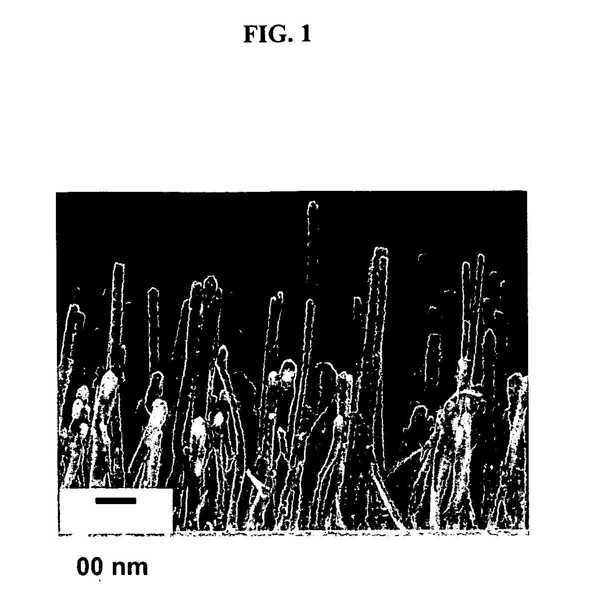
Synthesis of Vertically Aligned Carbon Nanofibers

[0033]Vertically aligned carbon nanofibers were grown using DC plasma-enhanced chemical vapor deposition (DC-PECVD) in a custom-built chamber. (See Cassell, A. M.; Ye, Q.; Cruden, B. A.; Li, J.; Sarrazin, P. C.; Ng, H. T.; Han, J.; Meyyappan, M. Nanotechnology 2004, 15, 9.) The nanofibers shown in FIG. 1 were grown on silicon nitride substrates that were covered with a thin multilayer film consisting of 50 nm of molybdenum, followed by 20 nm of titanium, and finally 20 nm nickel as the top layer. Typical growth conditions used flow rates of 80 standard cubic centimeters per minute (sccm) ammonia and 30 sccm acetylene, with a chamber pressure of 4 torr and a DC power of 360 watts. Under these growth conditions, the nanofibers have an average diameter ˜80 nm and are nearly cylindrical and are nearly all vertically aligned. The length of the fibers can be controlled with the time of growth. All fibers used here were grown for 15 minutes,...

example 2

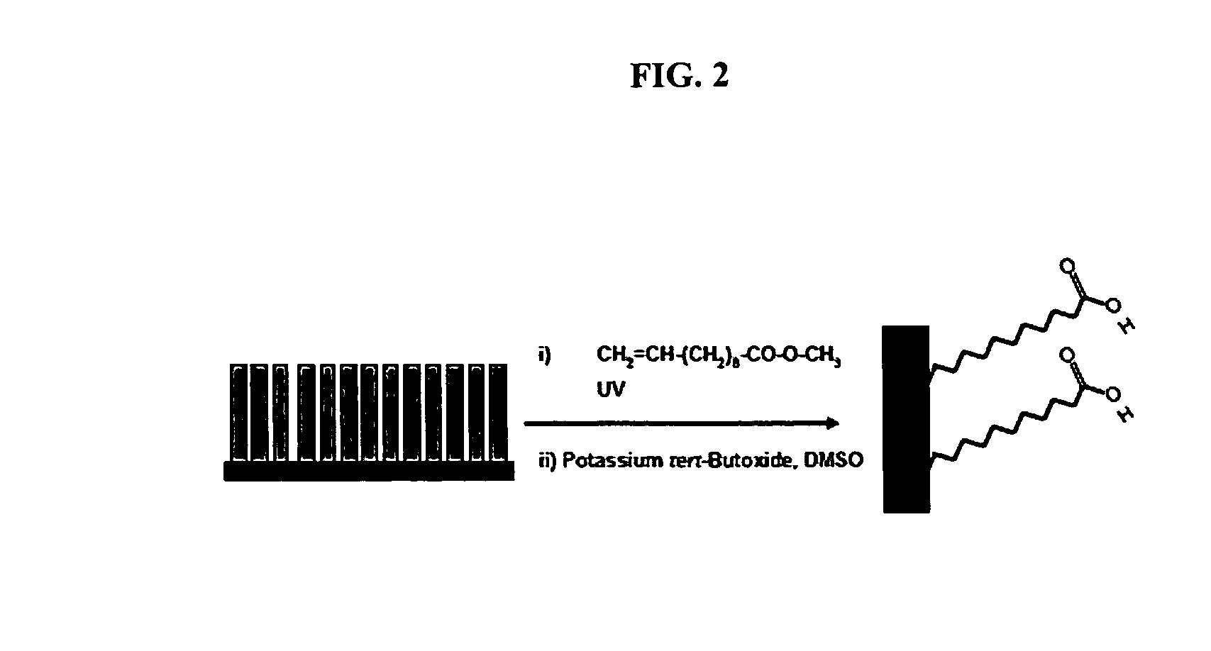
Functionalization of Vertically Aligned Carbon Nanofibers

[0034]Vertically aligned carbon nanofibers were functionalized with terminal reactive moieties as illustrated in FIG. 2. Specifically, carbon nanofibers were reacted with undecylenic acid methyl ester (Aldrich) in a quartz covered, nitrogen purged reaction chamber. Functionalization was carried out by sandwiching a drop of the ester between the sample and a small quartz window, used to minimize evaporation. The entire chamber was illuminated with 254 nm UV light for 16 to 18 hours. To remove non-covalently attached reactants, the samples were washed in chloroform for 30 minutes, and then immersed in methanol to rinse. These washing steps were performed twice. The ester was deprotected by reacting the samples in a potassium tert-butoxide slurry in DMSO (˜250 mg in ˜10 mL) for 5 minutes. Samples were then washed in 0.1 M HCl. Deprotection left the carbon nanofiber surfaces functionalized with terminal carboxylic acid moieties.

example 3

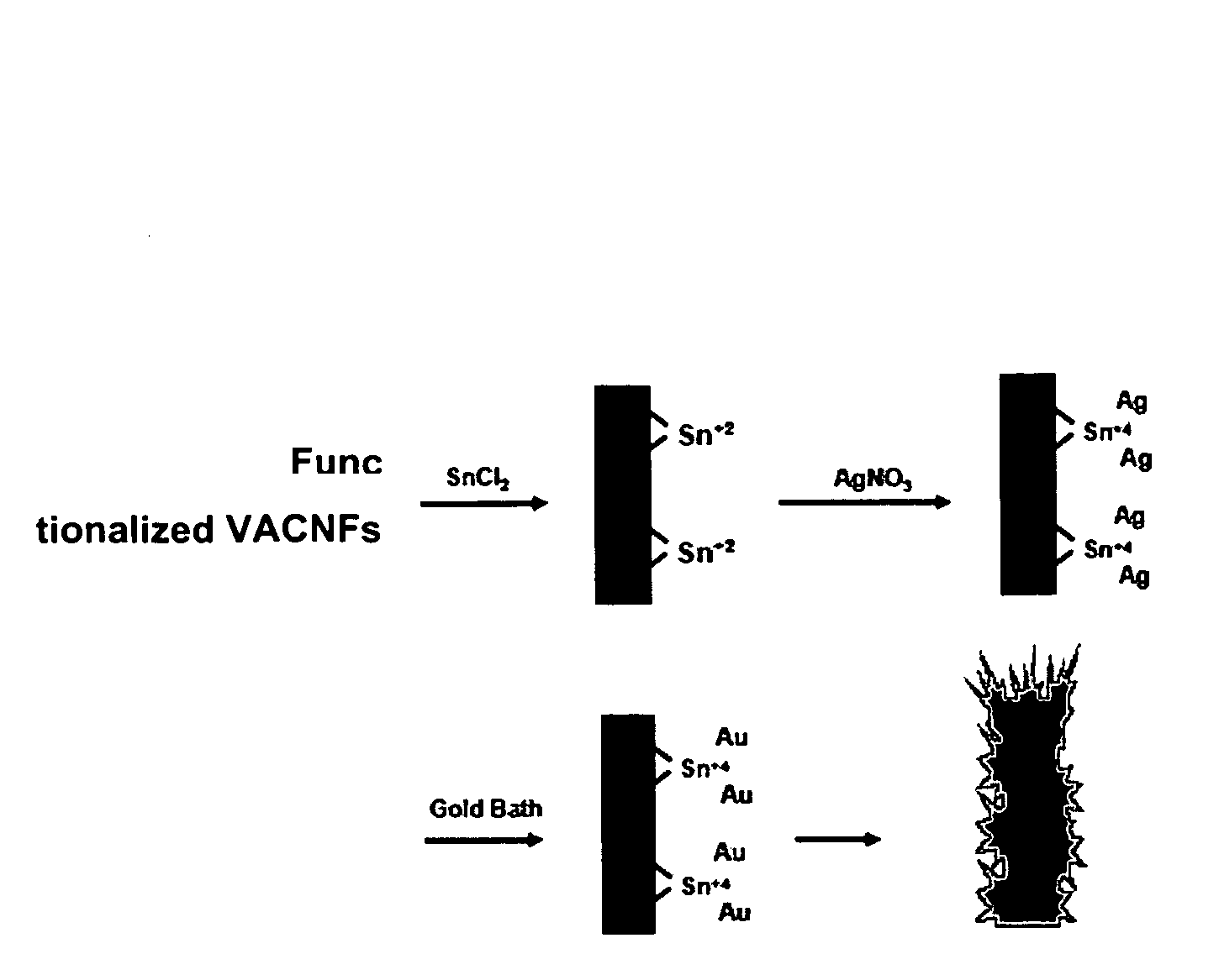
Preparation of Metal-Coated Vertically Aligned Carbon Nanofibers Using Electroless Deposition

[0035]Functionalized vertically aligned carbon nanofibers were coated with metal according to the scheme outlined in FIG. 3. Functionalized nanofibers were immersed in methanol and then in a tin sensitizing solution consisting of 0.026M SnCl2, and 0.07M trifluoroacetic acid in a 50:50 methanol:DI H2O solution for 45 minutes at room temperature. The samples were removed from the tin solution, rinsed by immersion in methanol, and then activated with silver by placing them in 5 mL of ammonical silver nitrate solution (0.03M AgNO3) for 15 minutes. The samples were removed from the silver nitrate solution and rinsed by immersion in methanol. The samples were then placed in individual gold baths in a refrigerator at 6° C. and left for 1 to 22 hours. The gold baths consisted of 0.127M Na2SO3, 0.025M NaHCO3, 0.625M formaldehyde and 8 mM Na2Au(SO3)2 (Technic Oromerse Part B gold solution). The pH of ...


PUM

PropertyMeasurementUnit
Diameteraaaaaaaaaa
Lengthaaaaaaaaaa
Densityaaaaaaaaaa

Abstract

The present invention provides electrodes comprised of metal-coated vertically aligned carbon nanofibers. Arrays of vertically aligned carbon nanofibers provide highly accessible, high density templates having large electrochemically active surface areas that may be modified to further increase the surface area of the nanofibers. The methods of the present invention involve functionalizing the surface of the nanofibers and coating the functionalized surface with metal using electroless deposition. The resulting metal-coated nanofibers form highly stable and highly reproducible electrodes having very high surface areas. The electrodes of the present invention are expected to be useful in a variety of applications, including high-density energy storage, i.e., supercapacitors and fuel cells.

Description

STATEMENT OF GOVERNMENT RIGHTS[0001]Research funding was provided for this invention by the National Science Foundation under grant No. NSF: 0210806. The United States government has certain rights in this invention.FIELD OF THE INVENTION[0002]The present invention provides metal-coated vertically aligned carbon nanofibers having very high surface areas and methods of making the metal-coated nanofibers using electroless deposition.BACKGROUND OF THE INVENTION[0003]High surface area materials have attracted much attention for their potential uses in electrocatalysis, batteries, fuel cells, and sensors. (See Arico, A. S.; Bruce, P.; Scrosati, B.; Tarascon, J. M.; Van Schalkwijk, W., Nanostructured Materials for Advanced Energy Conversion and Storage Devices. Nature Materials 2005, 4, (5), 366-377; Baughman, R. H.; Zakhidov, A. A.; de Heer, W. A., Carbon Nanotubes—The Route Toward Applications. Science 2002, 297, (5582), 787-792; Hutchings, G. J.; Haruta, M., A Golden Age Of Catalysis: ...

Claims


Application Information

Patent Timeline
IPC IPC(8): B32B9/00B05D5/12B32B3/00B82Y30/00B82Y40/00
CPCB82Y30/00H01G11/36H01M4/661H01M4/663H01M4/667H01M4/8605H01M4/8657H01M4/90H01M4/9083H01M4/92H01M4/926H01M2004/021Y02E60/13Y10T428/24917Y10T428/30Y02E60/50Y02E60/10
Inventor METZ, KEVIN MICHAELHAMERS, ROBERT J.
Owner WISCONSIN ALUMNI RES FOUND
Why Eureka
Try Eureka