
Electrochemical process for synthesis of graphene

a graphene and electrochemical technology, applied in the field of electrochemical route for the synthesis of graphene, can solve the problems of poor quality and yield, difficult control of both layer thickness and edge smoothness in an accurate manner, and limitations of solvothermal synthesis techniques, etc., to achieve uniform layer thickness and less defects

Inactive Publication Date: 2013-07-11
COUNCIL OF SCI & IND RES
View PDF1 Cites 12 Cited by
  • Summary
  • Abstract
  • Description
  • Claims
  • Application Information

AI Technical Summary

Benefits of technology

The patent describes a method for making high-quality graphene nanoribbons with good conductivity and mobility. Compared to other methods, this approach has advantages such as better quality and control over the degree and site of oxidation. By tuning the orientation and planes along the length, defects can be minimized. The method also allows for predictable control over edge smoothness and layer thickness. Overall, this method produces graphene nanoribbons with improved quality and performance.

Problems solved by technology

Reported techniques for the synthesis of graphene such as mechanical cleavage, silicon carbide sublimation, solvothermal synthesis, chemical vapour deposition, and plasma etching suffer from limitations such as, a) poor quality and yield (<2%) of graphene ribbons, b) formation of over oxidized and defective nanoribbons, c) substrate-dependant behavior and finally, d) difficulty of controlling both layer thickness and edge smoothness in an accurate manner.
However, these methods have several problems primarily involved with the selection of strong oxidizing agents.
The choice of the chemical oxidation route has issues such as over oxidation of edges that create defect sites which hamper electronic properties of graphene.
In addition the use of strong reducing agents may pose difficulties in controlling the layer thickness of graphene ribbons.
More significant would be the separation and disposal problem of these reagents with respect to the environment and hazardous effluent treatment.
Further, the process results in electrochemical oxidative scission of carbon nanotubes, the oxidation being optimally carried out at a positive electromotive force for 10 hours.
Thus it is observed that prior at documents combine processes such as chemical oxidation and reduction or chemical oxidation with electrochemical reduction to result in graphene, but with poor yields and poor characteristics.

Method used


Image

  • Electrochemical process for synthesis of graphene
  • Electrochemical process for synthesis of graphene
  • Electrochemical process for synthesis of graphene

Examples


example 1

[0052]10 mg of SWCNT (99% pure, Aldrich Company) was added to 20 ml of ethanol and 5 μl of 0.1% of Nafion (as binder). This solution was sonicated for 15 minutes to get complete dispersion. This was subsequently deposited onto conducting substrate, a glassy carbon electrode(GCE). Before the deposition, the glassy carbon electrode was polished with alumina powder, rinsed thoroughly in acetone, and finally dried. The deposition procedure involves spreading of a 5 μl portion on this pretreated bare GCE using a micropipette tip. This GCE was allowed to dry in an inert atomospere for 1 hour to form a thin uniform layer of CNT. The electrochemical oxidation of CNT was carried out in a three-electrode system (Pt as counter electrode, saturated Mercury Mercurous Sulphate as reference electrode) with the help of a dc power supply at fixed positive potential of 0.5, V for different periods such as 4, 8, 12 hours in 0.5 M H2SO4 The extent of oxidation was confirmed by various characterization ...

example 2

[0053]10 mg of MWCNT (99% pure, Aldrich Company) was added to 20 ml of ethanol and 5 μl of 0.1% of Nafion (as binder). This solution was sonicated for 15 minutes to get complete dispersion. A portion from this was subsequently deposited onto a conducting substrate, a glassy carbon electrode (GCE). Before the deposition, the glassy carbon electrode was polished with alumina powder, rinsed thoroughly in acetone, and finally dried. The deposition procedure involves spreading of a 5 μl portion on this pretreated bare GCE using a micropipette tip. This GCE was allowed to dry in an inert atomospere for 1 hour to form a thin uniform layer of CNT. The electrochemical oxidation of CNT was carried out in a three-electrode system (Pt as counter electrode, saturated Mercury Mercurous Sulphate as reference electrode) with the help of a dc power supply at fixed positive potential of 0.6 V for different periods such as 4, 8, 12 hours in 0.5 M H2SO4 The extent of oxidation was confirmed by various ...

example 3

[0054]10 mg of DWCNT (99% pure, Aldrich Company) was added to 20 ml of ethanol and 5 μl of 0.1% of Nafion (as binder). This solution was sonicated for 15 minutes to get complete dispersion. This was subsequently deposited onto conducting substrate, a glassy carbon electrode (GCE).

[0055]Before the deposition, the glassy carbon electrode was polished with alumina powder, rinsed thoroughly in acetone, and finally dried. The deposition procedure involves spreading of a 5 μl portion on this pretreated bare GCE using a micropipette tip. This GCE was allowed to dry in an inert atomospere for 1 hour to form a thin uniform layer of CNT. The electrochemical oxidation of CNT was carried out in a three-electrode system (Pt as counter electrode, saturated Mercury Mercurous Sulphate as reference electrode) with the help of a DC power supply at fixed positive potential of 0.8 V for different periods such as 4, 8, 12 hours in 0.5 M H2SO4 The extent of oxidation was confirmed by various characteriza...


PUM

PropertyMeasurementUnit
Fractionaaaaaaaaaa
Timeaaaaaaaaaa
Timeaaaaaaaaaa

Abstract

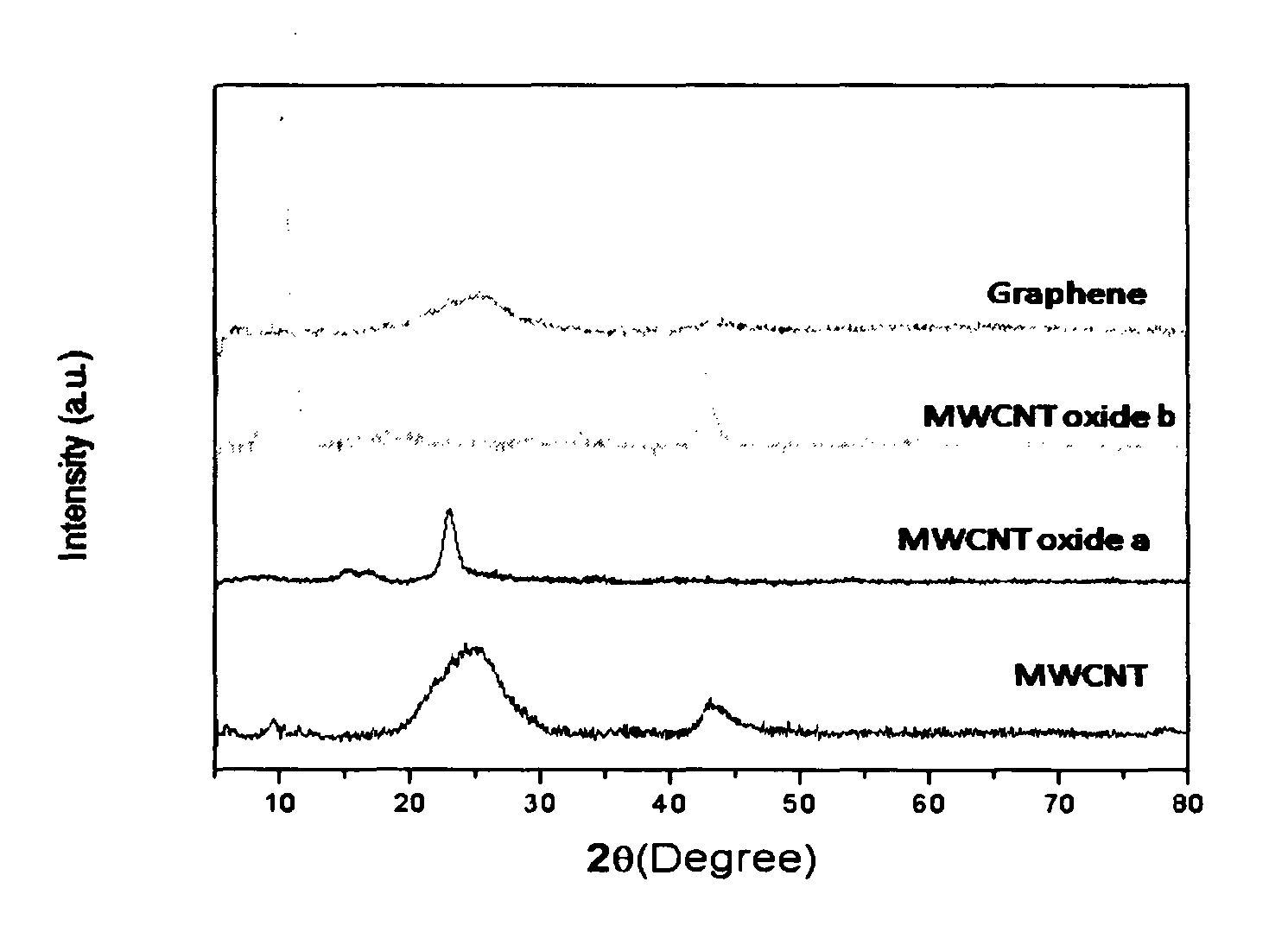
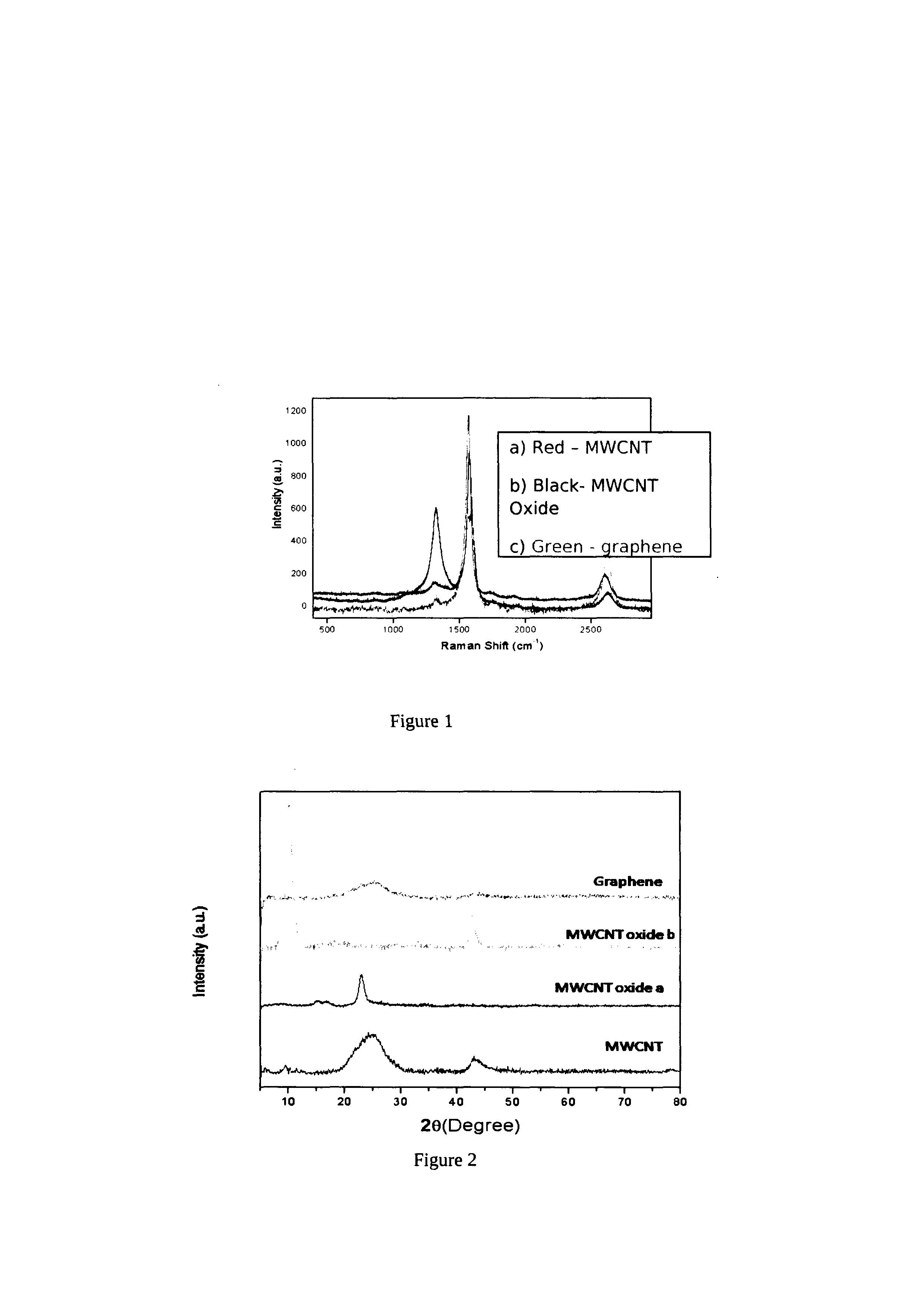
A process for the transformation of carbon nanotubes (CNTs) to nanoribbons composed of a few layers of graphene by a two-step electrochemical approach is disclosed in this invention. This consists of the oxidation of CNTs at controlled potential, followed by reduction to form graphene nanoribbons (GNRs) having smooth edges and fewer defects, as evidenced by multiple characterization techniques, including Raman spectroscopy, atomic force micro-scopy, and transmission electron microscopy. This type of ‘unzipping” of CNTs (single-walled, multi-walled) in the presence of an interfacial electric field provides unique advantages with respect to the orientation of CNTs, which might make possible the production of GNRs with controlled widths and fewer defects. The extent of oxidation was confirmed by various characterization techniques like XRD, XPS and Raman spectroscopy. In the second step of experiments, the CNT oxide were reduced for different periods such as 4, 8, 12 hours at fixed negative potentials of −0.5 V, so as to get layers of graphene ribbons as tabulated herein.

Description

FIELD OF THE INVENTION[0001]Present invention provides an electrochemical route for the synthesis of graphene. Present invention further relates to an electrochemical, two-step route to synthesize graphene from carbon Nanotubes (CNT5), and other hollow carbon nanostructures resulting in high yields.BACKGROUND AND PRIOR ART OF THE INVENTION[0002]Graphene is a flat monolayer of carbon atoms tightly packed into a two-dimensional (2D) honeycomb lattice, and is a basic building block for graphitic materials of all other dimensionalities with application in very exciting areas including integrated circuits, transistors, ultra capacitors, Li-ion batteries and bio-devices. Graphene exhibits many exciting properties, like room temperature quantum hall effect, long range ballistic transport with around ten times higher electron mobility than that in silicon, availability of charge carriers that behave as mass less relativistic quasi-particles like Dirac fermions, quantum confinement resulting...

Claims


Application Information

Patent Timeline
IPC IPC(8): C01B31/04
CPCB82Y30/00B82Y40/00C01B31/0438C25B1/00C01B31/0446C01B32/182C01B32/184C01B32/158C01B2202/02C01B2202/06C01B2202/04C01B2204/06
Inventor SHINDE, DHANRAJ BHAGWANRAOPILLAI, VIJAYMOHANAN KUNJIKRISHNAN
Owner COUNCIL OF SCI & IND RES
Learn More