

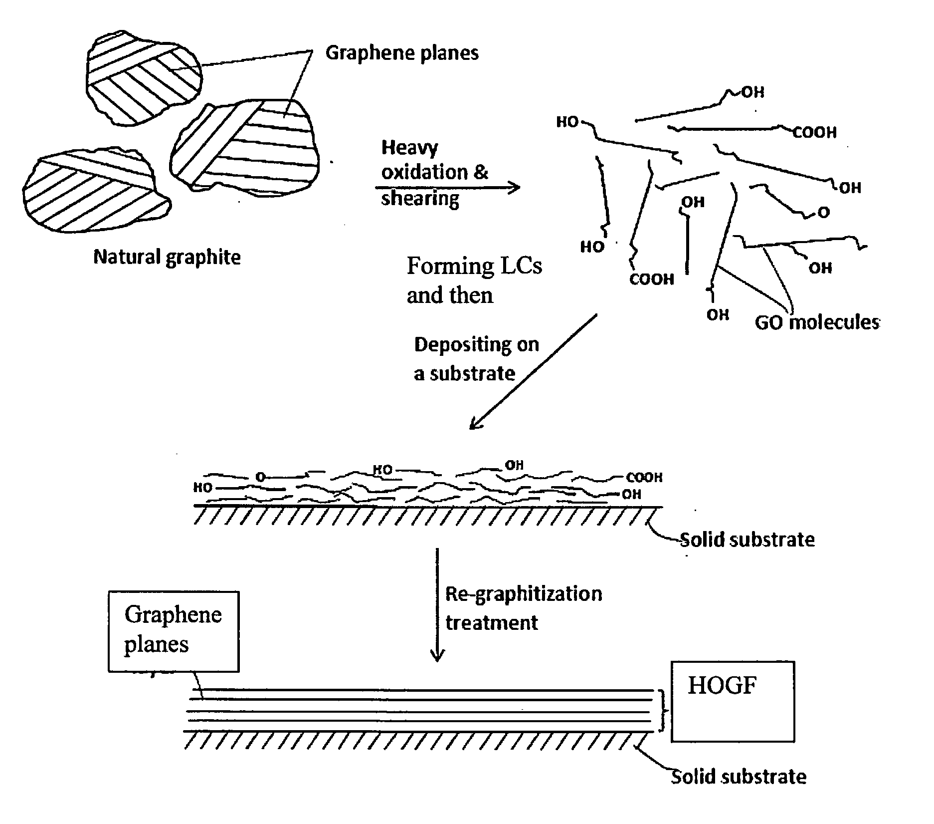
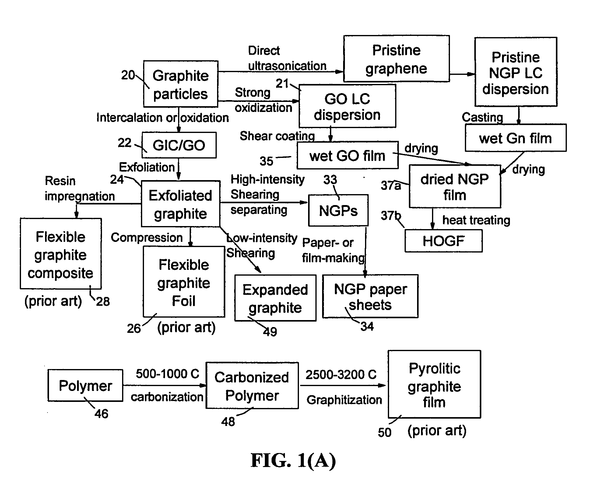
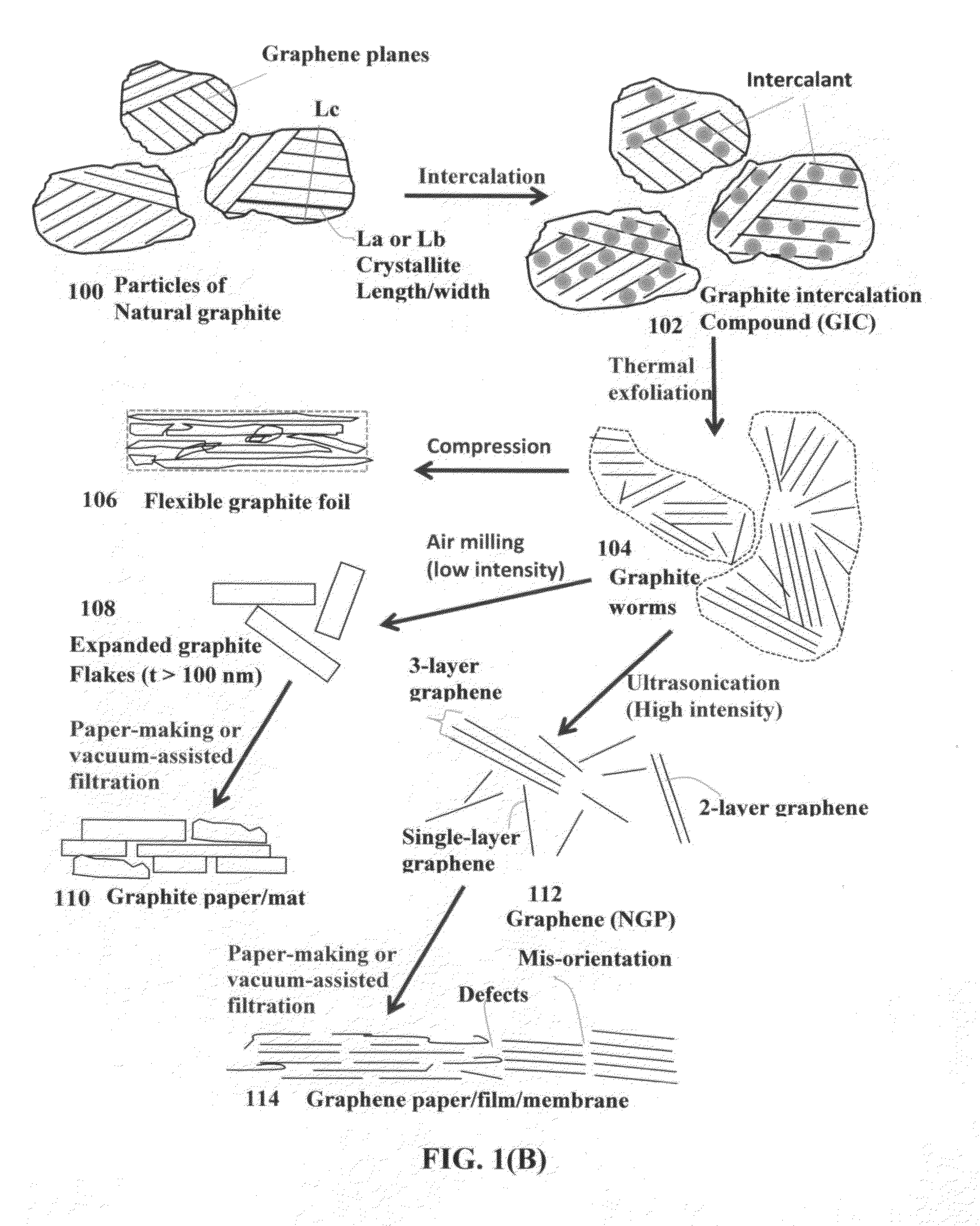
Process for producing highly conducting graphitic films from graphene liquid crystals
a graphene liquid crystal and graphene technology, applied in the field of graphitic materials, can solve the problems of inability to produce such a highly oriented graphitic film, inability to meet the requirements of high-temperature graphene liquid crystallization, so as to achieve the effect of increasing the density of the layer and reducing the thickness
- Summary
- Abstract
- Description
- Claims
- Application Information
AI Technical Summary
Benefits of technology
Problems solved by technology
Method used
Image

Examples
example 1
Preparation of GO Sheets and GO Liquid Crystals from Natural Graphite Powder
[0108]Natural graphite from Huadong Graphite Co. (Qingdao, China) was used as the starting material. GO was obtained by following the well-known modified Hummers method, which involved two oxidation stages. In a typical procedure, the first oxidation was achieved in the following conditions: 1100 mg of graphite was placed in a 1000 mL boiling flask. Then, 20 g of K2S2O8, 20 g of P2O5, and 400 mL of a concentrated aqueous solution of H2SO4 (96%) were added in the flask. The mixture was heated under reflux for 6 hours and then let without disturbing for 20 hours at room temperature. Oxidized graphite was filtered and rinsed with abundant distilled water until neutral pH. A wet cake-like material was recovered at the end of this first oxidation.
[0109]For the second oxidation process, the previously collected wet cake was placed in a boiling flask that contains 69 mL of a concentrated aqueous solution of H2SO4 (...
example 2
Preparation of Discrete GO Sheets from Graphite Fibers
[0111]Chopped graphite fibers with an average diameter of 12 μm and natural graphite particles were separately used as a starting material, which was immersed in a mixture of concentrated sulfuric acid, nitric acid, and potassium permanganate (as the chemical intercalate and oxidizer) to prepare graphite intercalation compounds (GICs). The starting material was first dried in a vacuum oven for 24 h at 80° C. Then, a mixture of concentrated sulfuric acid, fuming nitric acid, and potassium permanganate (at a weight ratio of 4:1:0.05) was slowly added, under appropriate cooling and stirring, to a three-neck flask containing fiber segments. After 5-16 hours of reaction, the acid-treated graphite fibers or natural graphite particles were filtered and washed thoroughly with deionized water until the pH level of the solution reached 6. After being dried at 100° C. overnight, the resulting graphite intercalation compound (GIC) or graphit...
example 3
Preparation of Single-Layer Graphene Sheets from Meso-Carbon Micro-Beads (MCMBs)
[0114]Meso-carbon micro-beads (MCMBs) were supplied from China Steel Chemical Co.; Kaohsiung, Taiwan. This material has a density of about 2.24 g / cm3 with a median particle size of about 16 μm. In one example, MCMB (10 grams) were intercalated with an acid solution (sulfuric acid, nitric acid, and potassium permanganate at a ratio of 4:1:0.05) for 48-96 hours. Upon completion of the reaction, the mixture was poured into deionized water and filtered. The intercalated MCMBs were repeatedly washed in a 5% solution of HCl to remove most of the sulphate ions. The sample was then washed repeatedly with deionized water until the pH of the filtrate was no less than 4.5. The slurry was then subjected ultrasonication for 10-100 minutes to fully exfoliate and separate GO sheets. TEM and atomic force microscopic studies indicate that most of the GO sheets were single-layer graphene when the oxidation treatment excee...
PUM
| Property | Measurement | Unit |
|---|---|---|
| physical density | aaaaa | aaaaa |
| thickness | aaaaa | aaaaa |
| thickness | aaaaa | aaaaa |
Abstract
Description
Claims
Application Information