
Method of Manufacturing a Lithium Secondary Battery Having a Protected High-Capacity Anode Active Material

a lithium secondary battery and high-capacity technology, applied in the field of rechargeable lithium batteries, can solve the problems of severe pulverization (fragmentation of alloy particles), loss of contacts between active material particles and conductive additives, etc., to achieve the effect of improving lithium ion conductivity to a polymer

Active Publication Date: 2018-08-16
GLOBAL GRAPHENE GRP INC
View PDF5 Cites 39 Cited by
  • Summary
  • Abstract
  • Description
  • Claims
  • Application Information

AI Technical Summary

Benefits of technology

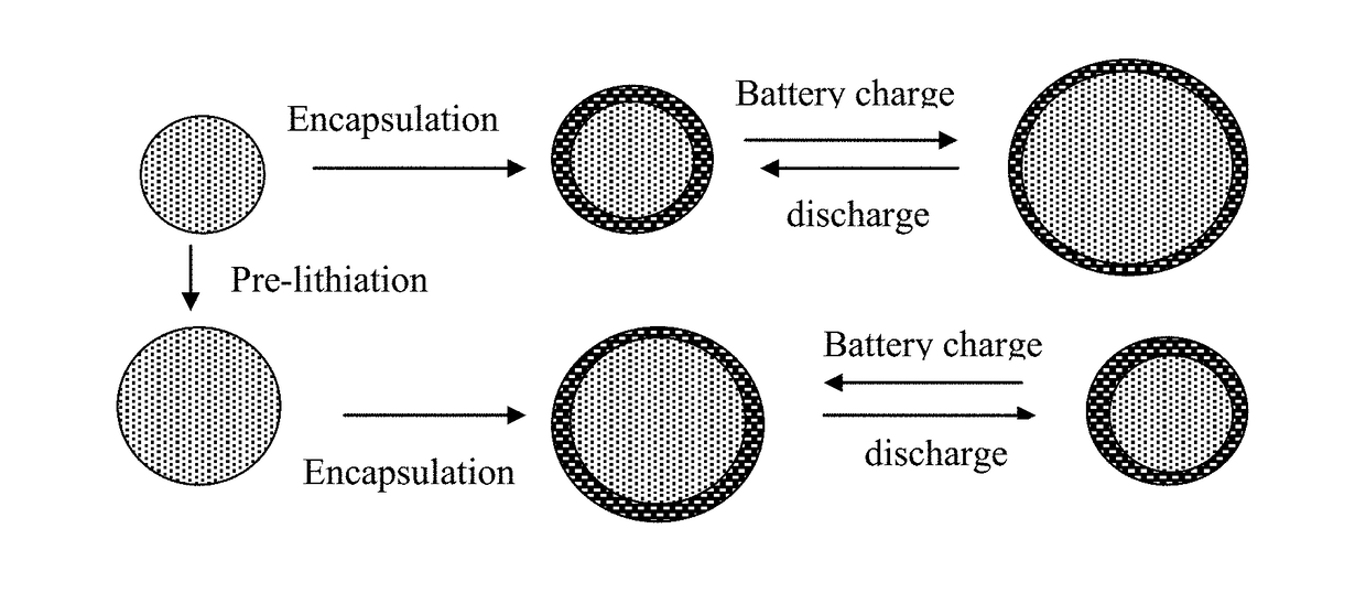
The present invention is about a new method for making lithium secondary batteries. The method involves using an anode made of multiple particles of a high-capacity anode active material, which is surrounded by a thin layer of an elastomeric material that prevents direct contact between the anode active material and the electrolyte, reducing breakage and re-formation of the solid-electrolyte interface on the anode active material surfaces. This results in improved performance and durability of the lithium battery. The method also involves using an optional cathode and a lithium ion-conducting electrolyte for the battery.

Problems solved by technology

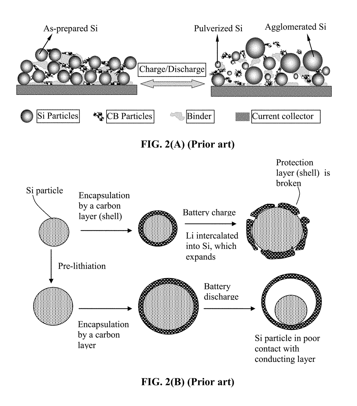
However, as schematically illustrated in FIG. 2(A), in an anode composed of these high-capacity materials, severe pulverization (fragmentation of the alloy particles) occurs during the charge and discharge cycles due to severe expansion and contraction of the anode active material particles induced by the insertion and extraction of the lithium ions in and out of these particles.
The expansion and contraction, and the resulting pulverization, of active material particles, lead to loss of contacts between active material particles and conductive additives and loss of contacts between the anode active material and its current collector.
These adverse effects result in a significantly shortened charge-discharge cycle life.
Such a reaction is undesirable since it is a source of irreversible capacity loss.(2) depositing the electrode active material in a thin film form directly onto a current collector, such as a copper foil.
However, such a thin film structure with an extremely small thickness-direction dimension (typically much smaller than 500 nm, often necessarily thinner than 100 nm) implies that only a small amount of active material can be incorporated in an electrode (given the same electrode or current collector surface area), providing a low total lithium storage capacity and low lithium storage capacity per unit electrode surface area (even though the capacity per unit mass can be large).
Such a thin-film battery has very limited scope of application.
Unfortunately, when an active material particle, such as Si particle, expands (e.g. up to a volume expansion of 380%) during the battery charge step, the protective coating is easily broken due to the mechanical weakness and / o brittleness of the protective coating materials.
There has been no high-strength and high-toughness material available that is itself also lithium ion conductive.
These protective materials are all very brittle, weak (of low strength), and / or non-conducting (e.g., ceramic or oxide coating).
(d) The protective material must not provide any significant amount of defect sites that irreversibly trap lithium ions.
The prior art protective materials all fall short of these requirements.
Furthermore, in most cases, the electrode was not capable of operating for a large number of cycles.
Additionally, most of these electrodes are not high-rate capable, exhibiting unacceptably low capacity at a high discharge rate.
Due to these and other reasons, most of prior art composite electrodes and electrode active materials have deficiencies in some ways, e.g., in most cases, less than satisfactory reversible capacity, poor cycling stability, high irreversible capacity, ineffectiveness in reducing the internal stress or strain during the lithium ion insertion and extraction steps, and other undesirable side effects.
It appears that carbon by itself is relatively weak and brittle and the presence of micron-sized graphite particles does not improve the mechanical integrity of carbon since graphite particles are themselves relatively weak.
Furthermore, polymeric carbon, amorphous carbon, or pre-graphitic carbon may have too many lithium-trapping sites that irreversibly capture lithium during the first few cycles, resulting in excessive irreversibility.
In summary, the prior art has not demonstrated a composite material that has all or most of the properties desired for use as an anode active material in a lithium-ion battery.

Method used


Image

  • Method of Manufacturing a Lithium Secondary Battery Having a Protected High-Capacity Anode Active Material
  • Method of Manufacturing a Lithium Secondary Battery Having a Protected High-Capacity Anode Active Material
  • Method of Manufacturing a Lithium Secondary Battery Having a Protected High-Capacity Anode Active Material

Examples


example 2

-Encapsulated Tin Oxide Particulates

[0100]Tin oxide (SnO2) nano particles were obtained by the controlled hydrolysis of SnCl4.5H2O with NaOH using the following procedure: SnCl4.5H2O (0.95 g, 2.7 m-mol) and NaOH (0.212 g, 5.3 m-mol) were dissolved in 50 mL of distilled water each. The NaOH solution was added drop-wise under vigorous stirring to the tin chloride solution at a rate of 1 mL / min. This solution was homogenized by sonication for 5 m in. Subsequently, the resulting hydrosol was reacted with H2SO4. To this mixed solution, few drops of 0.1 M of H2SO4 were added to flocculate the product. The precipitated solid was collected by centrifugation, washed with water and ethanol, and dried in vacuum. The dried product was heat-treated at 400° C. for 2 h under Ar atmosphere. A dilute elastomer-solvent solution (0.01-0.1 M of cis-polyisoprene in cyclohexane and 1,4-dioxane) was used as a coating solution in an air-suspension method to produce elastomer-encapsulated SnO2 particles hav...

example 3

Nano Particles Encapsulated by a Styrene-Butadiene Rubber (SBR)

[0102]Nano particles (76 nm in diameter) of Sn were encapsulated with a thin layer of SBR shell via the spray-drying method, followed by curing of the butadiene segment of the SBR chains to impart high elasticity to the SBR. For comparison, some amount of Sn nano particles was encapsulated by a carbon shell. Carbon encapsulation is well-known in the art. Un-protected Sn nano particles from the same batch were also investigated to determine and compare the cycling behaviors of the lithium-ion batteries containing these particles as the anode active material.

[0103]Shown in FIG. 7 are the discharge capacity curves of three coin cells having three different Sn particles as the anode active material: elastomer-encapsulated Sn particles, carbon-encapsulated Sn particles, and un-protected Sn particles. These results have clearly demonstrated that elastomer encapsulation strategy provides the very best protection against capacit...

example 4

re-Based Particulates

[0104]In a typical procedure, approximately 2.112 g of silicon powders (average diameter 2.64 μm) were mixed with 80 ml of a 0.1M aqueous solution of Ni(NO3).6H2O and vigorously stirred for 30 min. Then, water was evaporated in a rotary evaporator and the solid remnants were completely dried in an oven at 150° C. The final sample (Ni-impregnated Si powers) was obtained by grinding the solids in a mortar.

[0105]Subsequently, 0.03 g of Ni-impregnated Si particles was placed in a quartz boat, and the boat was placed in a tube furnace. The sample was reduced at 500° C. for 4 hours under flowing Ar (180 sccm) and H2 (20 sccm), then the temperature was raised to 990° C. to catalytically synthesize Si nanowires; Si nanowires were found to emanate from original micron-scaled Si particles. For the purpose of separating Si nanowires, for instance, every 0.1 g of the reacted Si powders was mixed with 10 ml of ethanol and the resulting mixture was sonicated for 1 hour. Subse...


PUM

PropertyMeasurementUnit
thicknessaaaaaaaaaa
lithium ion conductivityaaaaaaaaaa
diameteraaaaaaaaaa

Abstract

Provided is an anode active material layer for a lithium battery. This layer comprises multiple particulates of an anode active material, wherein at least a particulate is composed of one or a plurality of particles of a high-capacity anode active material being encapsulated by a thin layer of elastomeric material that has a lithium ion conductivity no less than 10−7 S / cm (preferably no less than 10−5 S / cm) at room temperature and an encapsulating shell thickness from 1 nm to 10 μm, and wherein the high-capacity anode active material (e.g. Si, Ge, Sn, SnO2, Co3O4, etc.) has a specific capacity of lithium storage greater than 372 mAh / g (the theoretical lithium storage limit of graphite).

Description

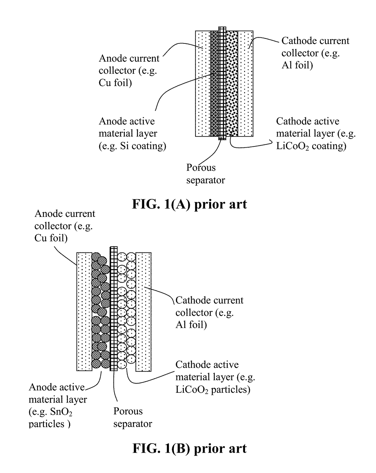
FIELD OF THE INVENTION[0001]The present invention relates generally to the field of rechargeable lithium battery and, more particularly, to the anode active materials in the form of elastomer-encapsulated particles and the process for producing same.BACKGROUND OF THE INVENTION[0002]A unit cell or building block of a lithium-ion battery is typically composed of an anode current collector, an anode or negative electrode layer (containing an anode active material responsible for storing lithium therein, a conductive additive, and a resin binder), an electrolyte and porous separator, a cathode or positive electrode layer (containing a cathode active material responsible for storing lithium therein, a conductive additive, and a resin binder), and a separate cathode current collector. The electrolyte is in ionic contact with both the anode active material and the cathode active material. A porous separator is not required if the electrolyte is a solid-state electrolyte.[0003]The binder in...

Claims


Application Information

Patent Timeline
Patent Type & Authority Applications(United States)
IPC IPC(8): H01M4/36H01M10/0525H01M4/62
CPCH01M4/366H01M2004/027H01M4/628H01M10/0525H01M4/62H01M4/405H01M4/386H01M4/364H01M4/587Y02E60/10Y02P70/50H01M4/139H01M10/058H01M10/052
Inventor ZHAMU, ARUNAJANG, BOR Z.
Owner GLOBAL GRAPHENE GRP INC
Learn More