

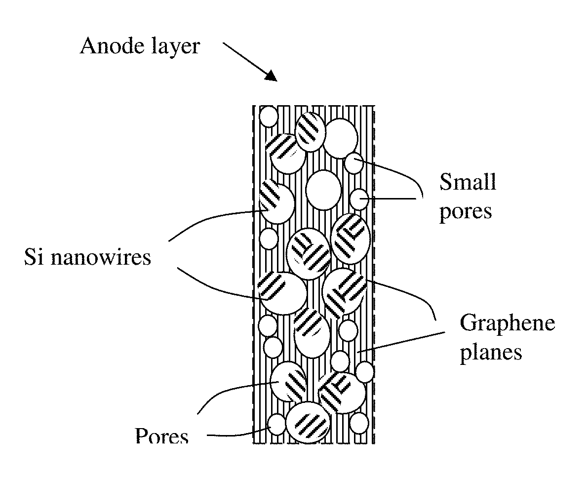
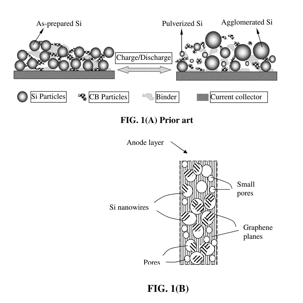
Lithium Ion Battery Anode Containing Silicon Nanowires Grown in situ in Pores of Graphene Foam and Production Process
a silicon nanowire, anode electrode technology, applied in the direction of cell components, electrochemical generators, impregnation manufacturing, etc., can solve the problems of severe pulverization (fragmentation of alloy particles), loss of contacts between active material particles and conductive additives, etc., to achieve faster transport of lithium ions, reduce interface resistance, and the effect of higher rate capability
- Summary
- Abstract
- Description
- Claims
- Application Information
AI Technical Summary
Benefits of technology
Problems solved by technology
Method used
Image

Examples
example 1
lowing Agents and Pore-Forming (Bubble-Producing) Processes
[0164]In the field of plastic processing, chemical blowing agents are mixed into the plastic pellets in the form of powder or pellets and dissolved at higher temperatures. Above a certain temperature specific for blowing agent dissolution, a gaseous reaction product (usually nitrogen or CO2) is generated, which acts as a blowing agent. However, a chemical blowing agent cannot be dissolved in a graphene material, which is a solid, not liquid. This presents a challenge to make use of a chemical blowing agent to generate pores or cells in a graphene material.
[0165]After extensive experimenting, we have discovered that practically any chemical blowing agent (e.g. in a powder or pellet form) can be used to create pores or bubbles in a dried layer of graphene when the first heat treatment temperature is sufficient to activate the blowing reaction. The chemical blowing agent (powder or pellets) may be dispersed in the liquid medium...
example 2
on of Discrete Functionalized GO Sheets and Graphene Foam
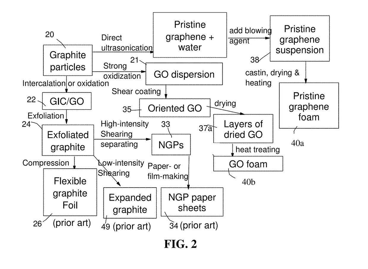
[0170]Chopped graphite fibers with an average diameter of 12 μm and natural graphite particles were separately used as a starting material, which was immersed in a mixture of concentrated sulfuric acid, nitric acid, and potassium permanganate (as the chemical intercalate and oxidizer) to prepare graphite intercalation compounds (GICs). The starting material was first dried in a vacuum oven for 24 h at 80° C. Then, a mixture of concentrated sulfuric acid, fuming nitric acid, and potassium permanganate (at a weight ratio of 4:1:0.05) was slowly added, under appropriate cooling and stirring, to a three-neck flask containing fiber segments. After 5-16 hours of reaction, the acid-treated graphite fibers or natural graphite particles were filtered and washed thoroughly with deionized water until the pH level of the solution reached 6. After a drying treatment at 100° C. overnight, the resulting graphite intercalation compound (GIC) ...
example 3
on of Single-Layer Graphene Sheets from Mesocarbon Microbeads (MCMBs) and Graphene Foam
[0173]Mesocarbon microbeads (MCMBs) were supplied from China Steel Chemical Co., Kaohsiung, Taiwan. This material has a density of about 2.24 g / cm3 with a median particle size of about 16 μm. MCMB (10 grams) were intercalated with an acid solution (sulfuric acid, nitric acid, and potassium permanganate at a ratio of 4:1:0.05) for 48-96 hours. Upon completion of the reaction, the mixture was poured into deionized water and filtered. The intercalated MCMBs were repeatedly washed in a 5% solution of HCl to remove most of the sulfate ions. The sample was then washed repeatedly with deionized water until the pH of the filtrate was no less than 4.5. The slurry was then subjected ultrasonication for 10-100 minutes to produce GO suspensions. TEM and atomic force microscopic studies indicate that most of the GO sheets were single-layer graphene when the oxidation treatment exceeded 72 hours, and 2- or 3-la...
PUM
| Property | Measurement | Unit |
|---|---|---|
| diameter | aaaaa | aaaaa |
| temperature | aaaaa | aaaaa |
| diameter | aaaaa | aaaaa |
Abstract
Description
Claims
Application Information