
Method of amplifying optical signals using doped materials with extremely broad bandwidths

a technology of doped materials and optical signals, applied in the direction of electromagnetic transmission, transmission, active medium materials, etc., can solve the problems of undesirable signal loss mechanism, further extending this limit,

Inactive Publication Date: 2002-12-03
THE BOARD OF TRUSTEES OF THE LELAND STANFORD JUNIOR UNIV
View PDF12 Cites 52 Cited by
  • Summary
  • Abstract
  • Description
  • Claims
  • Application Information

AI Technical Summary

Benefits of technology

One embodiment of this fiber synthesis method uses containerless processing techniques which avoid heterogeneous nucleation by contact with solid container walls and allow deep undercooling to a temperature below the melting point of the crystalline precursor material. The containerless processing techniques eliminate chemical contamination of the liquid by contact to an external object (such as a crucible). They can also be used to synthesize glass spheroids 2-3 millimeters in diameter from a variety of oxide materials. (See, for example, J. K. R. Weber, et al., Enhanced Formation of Calcia-Gallia Glass by Containerless Processing, J. Am. Ceram. Soc. Vol. 76, No. 9, 1993, pp. 2139-2141; and J. K. R. Weber, et al., Aero-acoustic levitation--A method for containerless liquid-phase processing at high temperatures, Rev. Sci. Instrumen., Vol. 65, 1994, pp. 456-465.) The new fiber fabrication process has been applied to a variety of oxide materials that contain neither silicon dioxide (silica) nor any of the other "network" formers that are typical components of the glass fibers made by conventional fiber fabrication techniques. This process allows the generation of fibers typically 10 to 30 microns in diameter and up to a meter in length.
The method described in WO 97 / 25284 permits high purity fibers to be manufactured from a number of materials that are known to exhibit high strength and stiffness, low creep rates, high oxidation resistance, or chemical compatibility with the components of composite materials at high temperatures. It allows fibers to be formed from materials that exhibit low absorption of electromagnetic radiation, such as but not limited to those used in telecommunications applications, and as fiber optic light guides, and from high purity materials. The method disclosed in WO 97 / 25284 also allows synthesis of homogeneous glass fibers which may include high concentrations of dopant elements for uses such as but not limited to fiber laser and fiber laser amplifier applications. According to WO 97 / 25284, the fibers may be drawn rapidly, enabling less expensive production, and may be crystallized to form stable materials which may be used, for example, in oxidation-resistant composite materials with very high temperature structural applications such as turbine combustion chamber liners and thrust deflectors. The method of WO 97 / 25284 also allows the synthesis of fibers with improved tensile strength and stiffness for use in polymer-matrix composite materials applications. In addition, the method of WO 97 / 25284 allows fibers to be formed from bio-compatible materials for in vivo medical applications. Thus, the method of WO 97 / 25284 greatly expands the range of materials that can be made into fibers by drawing from liquid melts.

Problems solved by technology

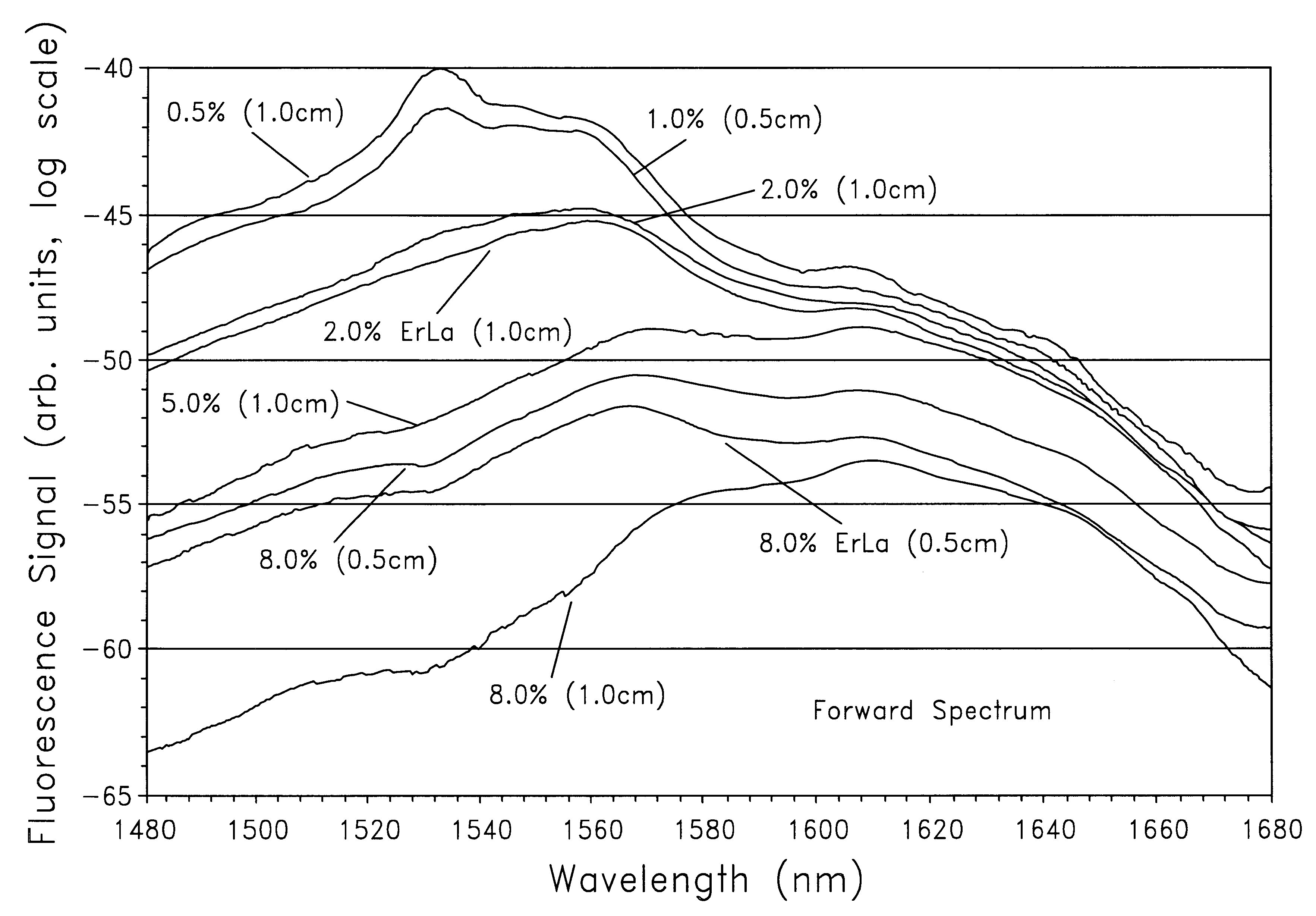
The difficulty in further extending this limit resides in the presence of signal excited-state absorption (ESA) above around 1,620 nanometers for tellurite glass and above around 1,610 nanometers for silica glass.
The ESA constitutes an undesirable signal loss mechanism.

Method used


Image

  • Method of amplifying optical signals using doped materials with extremely broad bandwidths
  • Method of amplifying optical signals using doped materials with extremely broad bandwidths
  • Method of amplifying optical signals using doped materials with extremely broad bandwidths

Examples


example 2

Fiber Drawing Using the Conical Nozzle Levitator

FIG. 18 shows the arrangement for drawing fibers from melts using a motor and wheel assembly and a conical nozzle levitation (CNL) device, to levitate and draw fibers from 0.25-0.40 cm diameter specimens, although larger specimens may be levitated depending upon their surface tension and density. A levitation gas flow 8 passes through a plenum chamber 9, through the nozzle 10 and over the levitated specimen 11. The levitated specimens are heated and melted with a CO.sub.2 laser beam 12 focused with a ZnSe lens 13 onto the top surface of the specimen. The temperature of the specimen is controlled by blocking the laser heating beam using any available means of signal blocking or by changes in the laser power. Fibers 76 are drawn from the bottom surface of the undercooled melts, using a tungsten wire stinger 77 that is fed through the nozzle and driven by a reversible stepper motor and wheel assembly 14. The stinger comprises a long tungs...

example 3

Drawing Fibers from Mullite Melts

FIG. 19 illustrates the time and temperature conditions under which fibers are drawn from undercooled melts of the mullite composition, 60:40 mole fraction of Al.sub.2 O.sub.3 :SiO.sub.2, using the fiber drawing methods of WO 97 / 25284.

FIG. 19 shows the typical temperature-time history of a levitated sample during fiber drawing experiments as a plot of the temperature measured with the optical pyrometer as a function of time. Prior to the illustrated time period, the specimen is melted with a CO.sub.2 laser beam and simultaneously levitated in an AAL apparatus in a flow of argon gas, and held at a constant temperature. The temperature range for fiber drawing is determined by drawing fibers at various temperatures using the fiber stinging and drawing device illustrated in FIG. 16 and described in Example 1. The decrease in temperature with time from 0 to 2.0 seconds of the recorded time interval shows cooling of the liquid upon blocking of the laser he...

example 4

Fibers Drawn From Undercooled Melts using Contained Systems

The description in WO 97 / 25284 also contemplates fibers drawn in contained systems. FIG. 21 illustrates a preferred embodiment of a method of supporting a liquid using a container which facilitates fiber drawing from undercooled melts without recrystallization. An important feature of the method includes establishing and maintaining a temperature gradient within the container, such that part of the molten mass is undercooled. In this method, the material of interest 30 is placed within an open container 22 such as a crucible, which container is maintained at a temperature above the melting point. A cover 25, also maintained at a temperature above the melting point, may be initially placed on the container to achieve thermal equilibrium inside the container and complete melting of the material. The cover may then be raised or removed, permitting heat loss and cooling of the melt surface. The heat transfer conditions at the me...


PUM


Abstract

In a method of amplifying optical input signals over a wide bandwidth, the optical input signals are applied to an optical waveguide made from a rare-earth-doped amorphous material (e.g., erbium-doped yttrium aluminum oxide material). The optical input signals include optical signals having wavelengths over a range of at least 80 nanometers, and, preferably, over a range of at least 160 nanometers. Pump light is applied to the optical waveguide to cause the waveguide to provide optical gain to the optical input signals. The optical gain causes the optical signals to be amplified within the waveguide to provide amplified optical signals over the extended 80-160-nanometer range, including, in particular, optical signals having wavelengths at one end of the range and optical signals having wavelengths at a second end or the range.

Description

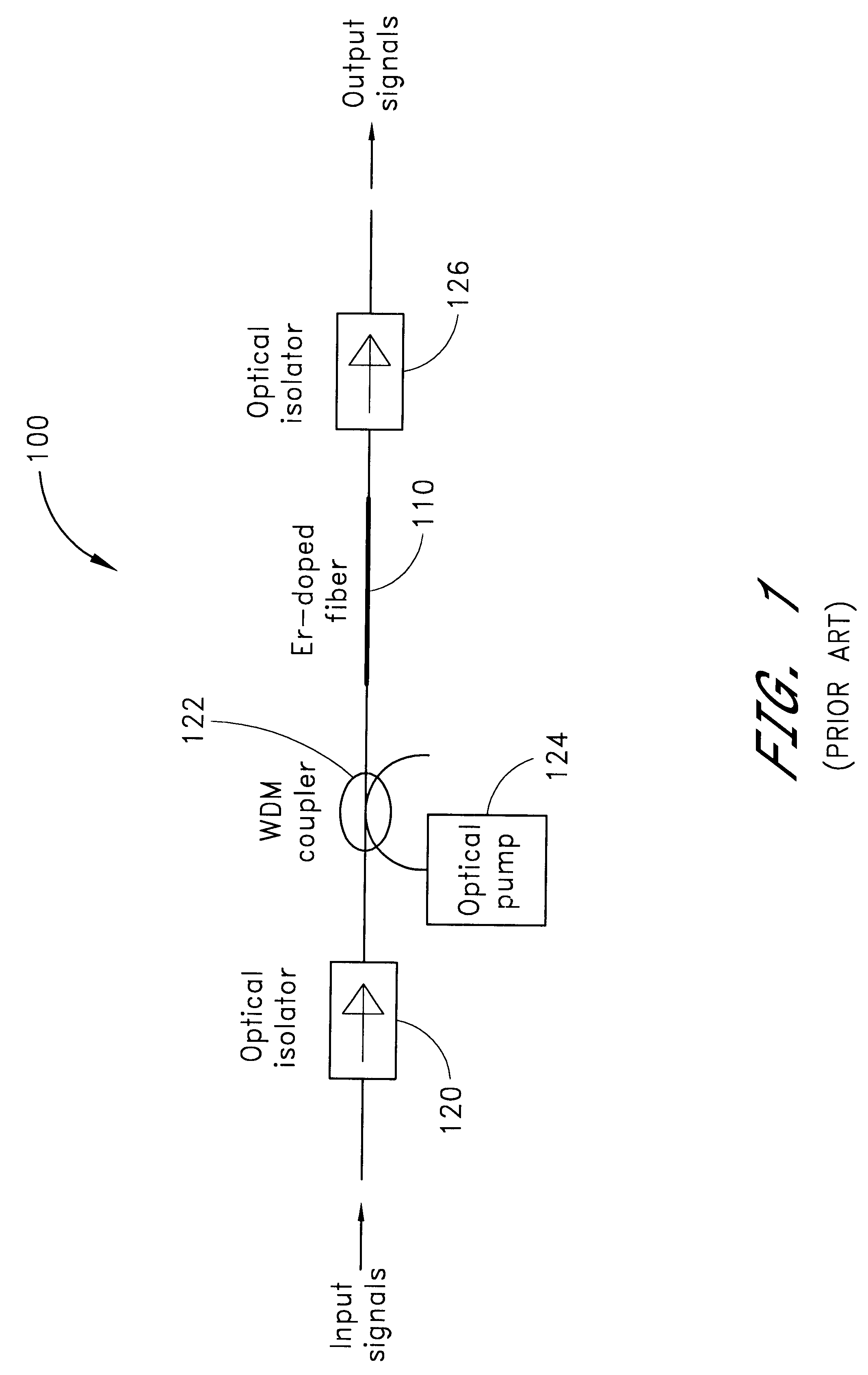
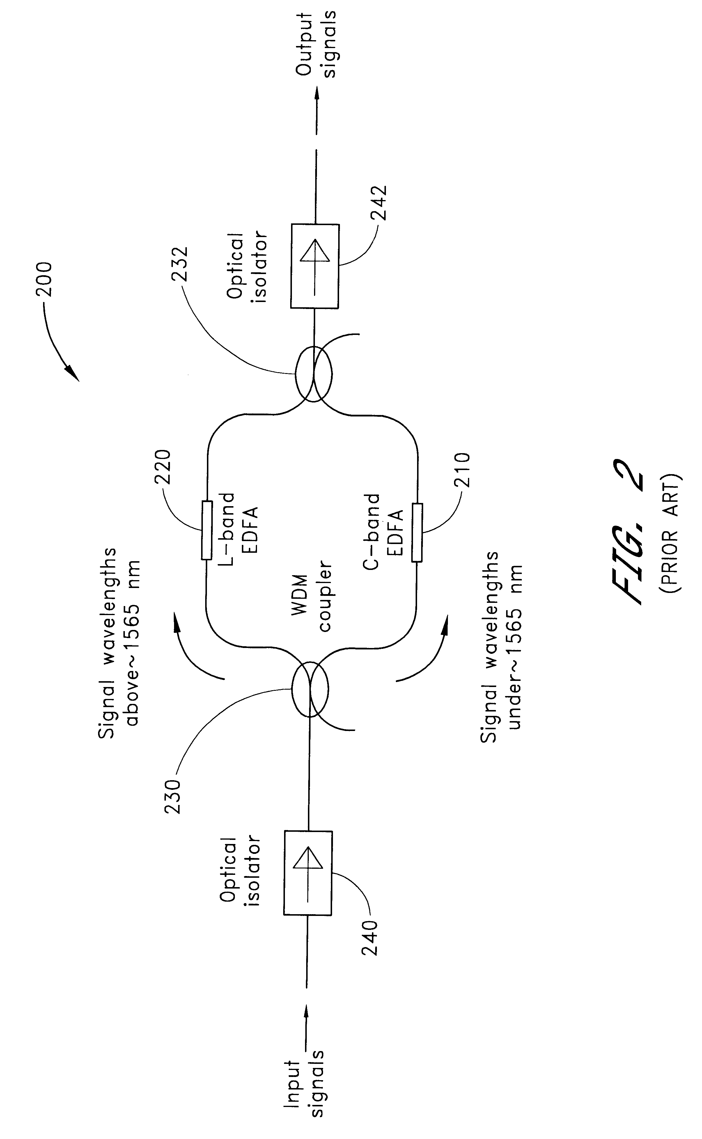
1. Field of the InventionThe present invention relates to the field of optical amplifiers, and, more particularly, relates to the field of optical amplifiers comprising a length of optical fiber having an active dopant which fluoresces in response to pump light.2. Description of the Related ArtErbium-doped fiber amplifiers (EDFAs) are used extensively in commercial optical communication systems, both as all-optical repeaters and pre-amplifiers. After traveling through long lengths of communication fiber (typically several tens of kilometers), the information-encoded signals are strongly attenuated by fiber loss, and it is the role of the erbium-doped fiber amplifier (EDFA) to amplify the signals to a reasonable power level. EDFAs have now reached the point where they have been optimized with respect to their energy efficiency to minimize their requirement for pump power (which is costly). EDFAs have further been optimized with respect to their noise performance such that noise figur...

Claims


Application Information

Patent Timeline
Patent Type & Authority Patents(United States)
IPC IPC(8): H01S3/06H01S3/067H01S3/16H01S3/094
CPCH01S3/06754H01S3/06766H01S3/0677H01S3/094011H01S3/094096H01S3/1608H01S3/1643
Inventor FEILLENS, YANNICK G.DIGONNET, MICHEL J. F.FEJER, MARTIN M.
Owner THE BOARD OF TRUSTEES OF THE LELAND STANFORD JUNIOR UNIV
Learn More