Conductive composition precursor, conductive composition, solid electrolytic capacitor, and their manufacturing method

Inactive Publication Date: 2005-02-08
PANASONIC CORP
View PDF10 Cites 45 Cited by
  • Summary
  • Abstract
  • Description
  • Claims
  • Application Information

AI Technical Summary

Benefits of technology

The present invention also applies at least one coupling agent selected from the group of: silane coupling agent, titanium coupling agent, borane coupling agent, or aluminum coupling agent to the surface of the anodized layer for providing an extremely thin insulating layer between the anodized layer and conductive polymer. Provision of a coupling agent layer and a layer made

Problems solved by technology

Downsizing of these capacitors, however, is difficult to reconcile with maintenance of large capacity.
On the other hand, thin anodized layers are fragile, and thus these capacitors require electrolytic substances to allow them to repair themselves.
This liquid electrolyte has ion conductivity and large specific resistance, resulting in large losses which significantly degrade the frequency characteristics as well as the impedance and temperature characteristics.
Moreover, leakage of liquid and evaporation of solvent are inevitable, resulting in reduced capacitance and increased loss as time passes.
However, the relatively high specific resistance of manganese oxide results in poor impedance frequency characteristics compared to multi-layered ceramic capacitors and film capacitors.
Application of electro-polymerization puts a limit on mass production because conductive polymer are formed on an electrode in a film.
However, the strategy of increasing the anodization voltage during the formation of the dielectric layer to allow a sufficient margin against the applied voltage with the aim of securing a high withstand voltage thickens the dielectric layer in proportion to the rated voltage

Method used


Image

  • Conductive composition precursor, conductive composition, solid electrolytic capacitor, and their manufacturing method
  • Conductive composition precursor, conductive composition, solid electrolytic capacitor, and their manufacturing method
  • Conductive composition precursor, conductive composition, solid electrolytic capacitor, and their manufacturing method

Examples


first exemplary embodiment

Whether the conductive polymer used for the present invention takes the form of particles dispersed in the medium or an intrinsic solution is a matter of controversy.

For convenience, in the following explanation of the invention, a ‘conductive polymer solution’ refers to both of the dispersion and solution. In the same way, for convenience, additives are also referred to as being “dissolved”, including those dispersed in a colloidal state.

A series of methods for manufacturing the conductive polymer solution used in the present invention are already disclosed, and thus the applicable conductive polymer solution can be easily manufactured using these disclosed methods.

For example, methods of manufacturing poly-pyrroles are disclosed in Japanese Patent Laid-open Publication No. H6-206986 and by E. E. Havinga et al, Chemistry of Materials (American Chemical Society), 1 (6), pp650 (1989).

F. Yonas et al, Synthetic Metals(Elsevia Press), 85, 1397 and Hotta et al, ibid, 26, 267 disclose the...

example 1

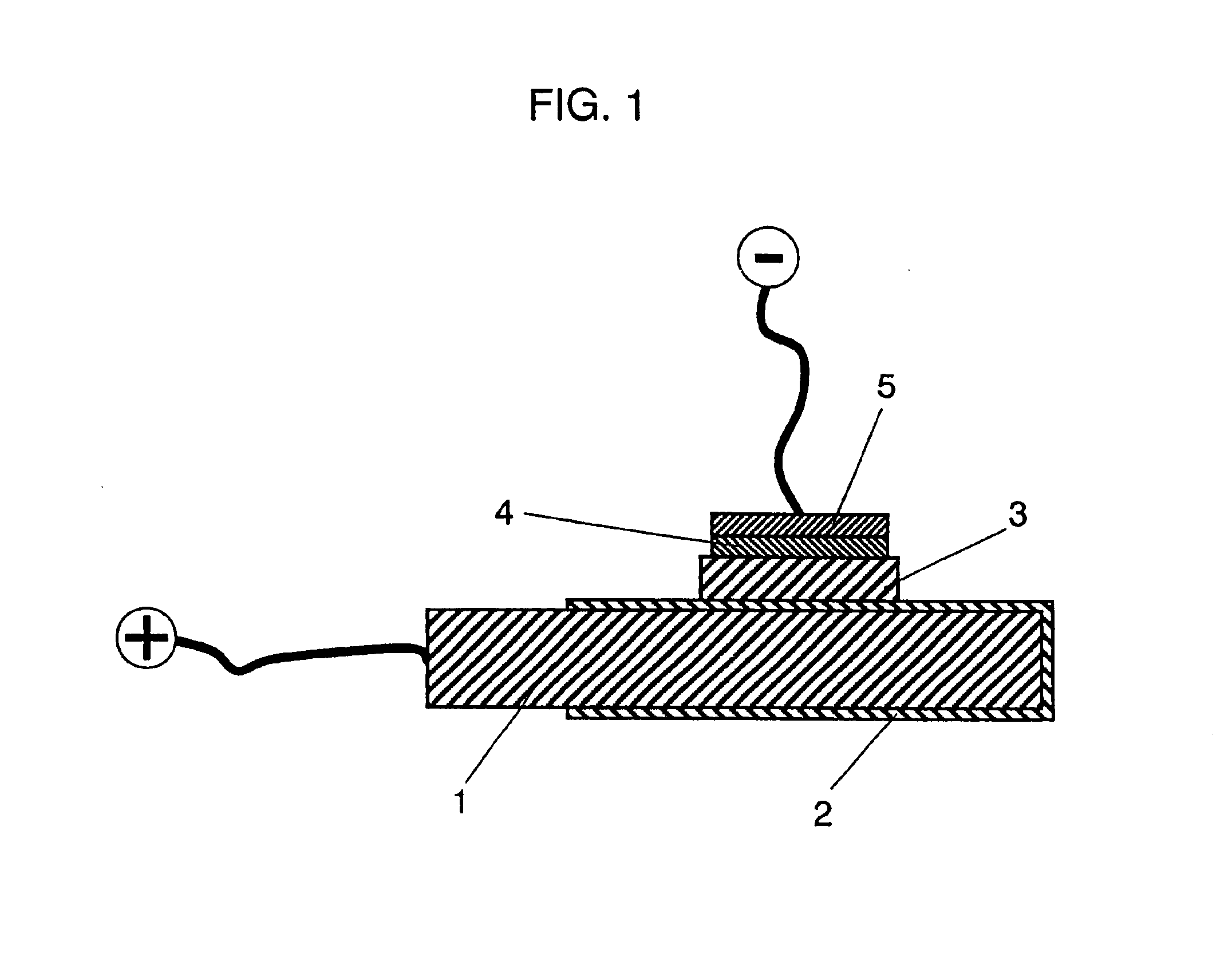
Example 1 is described with reference to FIG. 1.

First, poly-pyrrole solution is prepared using the method disclosed in Chemistry of Materials (American Chemical Society), 1 (6), pp650 (1989). Conductive composition precursor containing poly-pyrrole, ortho-phosphoric acid, and medium is prepared by adding 0.01% of ortho-phosphoric acid to this poly-pyrrole solution.

The precursor is a smooth liquid similar to the solution without ortho-phosphoric acid. It also enables the creation of a conductive composition layer equivalent to that without additive when the precursor is applied to the substrate and the medium is then dried and removed.

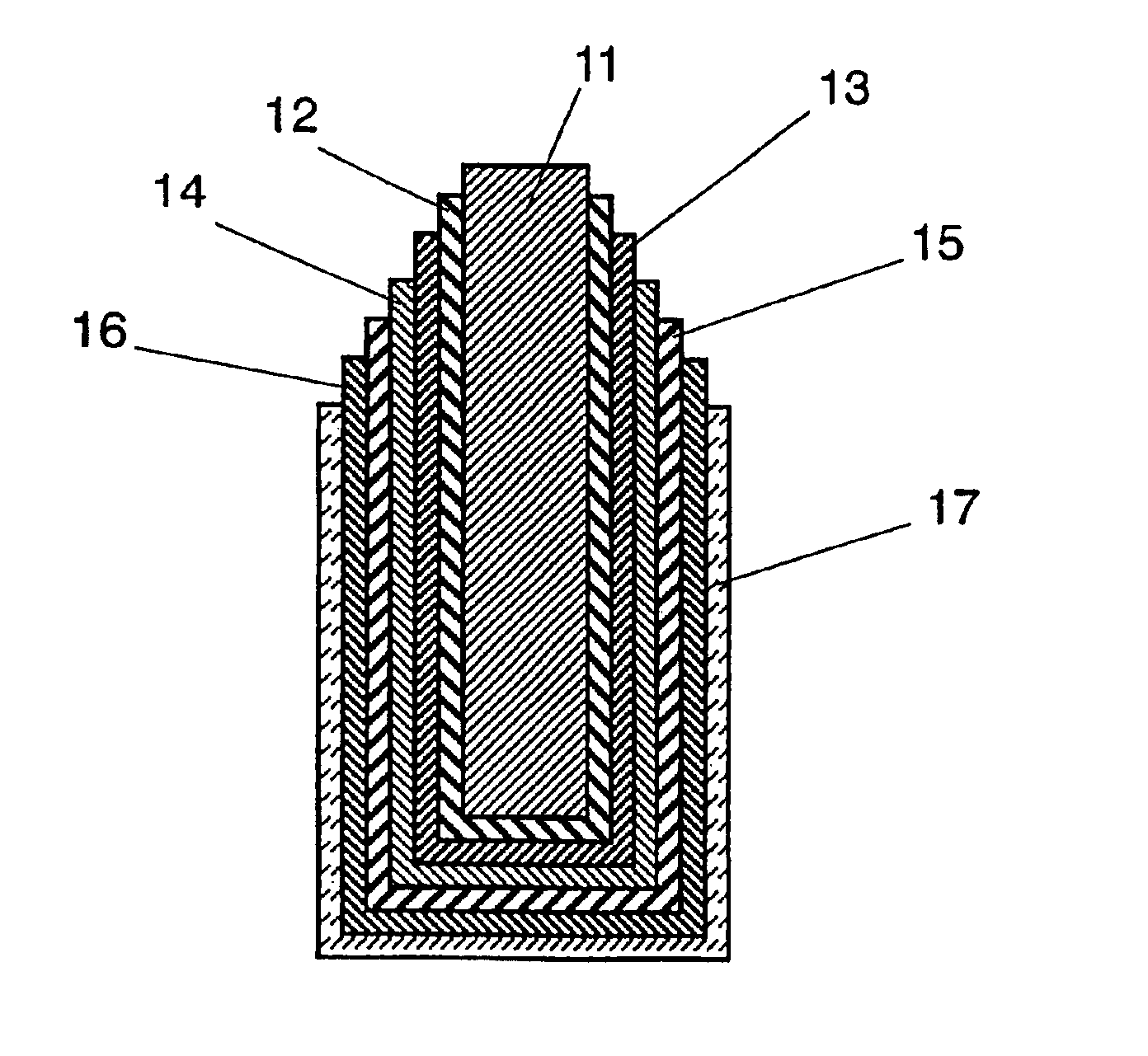
Next, as shown in FIG. 1, an aluminum strip 1 of 99.99% purity and dimensions of 10×30×0.5 mm is prepared. After electrolytic polishing of aluminum strip 1 in sodium hydroxide solution, the strip is dipped in 3% ammonium adipate solution to a depth of approximately 20 mm, and voltage of 35 V is applied for 30 minutes at 70° C. to form anodized film 2.

Th...

example 2

Example 2 shows the effects of addition of (A) n-propyl phosphoric acid, (B) isopropyl phosphoric acid, (C) n-butyl phosphoric acid, or (D) n-hexyl phosphoric acid, instead of ortho-phosphoric acid as seen in Example 1. Other conditions are the same as those in Example 1 for preparing conductive composition precursor.

These precursors are also smooth liquid similar to those containing no additives. A conductive composition layer identical to that with no additives is also provided by applying these precursors to a substrate, and drying and removing the medium. A capacitor is manufactured in the same way as that in Example 1 using each of these precursors, and the same evaluations as those in Example 1 are implemented.

The results are shown in Table 1. It is apparent that all the capacitors in Example 2 have a higher withstand voltage than that in Comparative example 1, demonstrating the advantageous effect of the present invention.


PUM

PropertyMeasurementUnit
Electrical conductoraaaaaaaaaa
Hydrophobicityaaaaaaaaaa
Surface activityaaaaaaaaaa

Abstract

A solid electrolytic capacitor including a valve metal positive electrode, an anodized layer formed on a surface of the positive electrode, a conductive polymer-containing negative electrode conductive layer, and a coupling agent layer and a surface active agent layer placed between the anodized layer and the negative electrode conductive layer.

Description

FIELD OF THE INVENTIONThe present invention relates to conductive composition precursors, conductive compositions, solid electrolytic capacitors, and their manufacturing methods, and more particularly to conductive compositions with high dielectric layer repairing ability and solid electrolytic capacitors with good withstand voltage employing such conductive compositions.BACKGROUND OF THE INVENTIONDemand for small high-capacitance capacitors with low impedance at high frequencies is growing in response to the increasing digitization of electric appliances. Conventional capacitors used at high frequencies include mica capacitors and multi-layered ceramic capacitors. Downsizing of these capacitors, however, is difficult to reconcile with maintenance of large capacity.Typical large-capacitance capacitors are electrolytic capacitors such as aluminum electrolytic capacitors and aluminum or tantalum solid electrolytic capacitors. The extremely thin anodized layer which becomes the dielect...

Claims


Application Information

Patent Timeline
IPC IPC(8): H01G9/02H01B1/12H01G9/025
CPCH01B1/127H01B1/128H01G9/025H01G9/028H01G11/56H01G11/48H01G11/54Y10T29/417Y02E60/13
Inventor KUDOH, YASUOAKAMI, KENJIKUSAYANAGI, HIROKIMATSUYA, YASUE
Owner PANASONIC CORP
Why Eureka
Try Eureka