Apparatus and method for photocatalytic purification and disinfection of fluids

Inactive Publication Date: 2005-06-07
FLUID LINES
View PDF29 Cites 65 Cited by
  • Summary
  • Abstract
  • Description
  • Claims
  • Application Information

AI Technical Summary

Benefits of technology

[0020]The effectiveness of the process is determined in part by the mass transfer efficiency, which is the rate at which the contaminant is transported from the fluid stream to the photocatalytic surface where it may be destroyed. The embodiment consisting of a semitransparent packing/semiconductor pairing provides for high specific surface area and adequate contacting of the surfaces with the treated fluid. The characteristic length associated with the substrate (packing) is kept as small as practical, within the constraint placed by allowable fluid pressure drop across the device.
[0021]Another consideration is the distribution of light to the semiconductor surfaces within the device. Since the semiconductor coating is semitransparent to the activating light, a portion of the photons are absorbed by the photocatalyst coated on the substrate, or within the substrate, and the remainder are passed onto an adjacent photocatalytic surface. Thus, the volume fraction of support material should be minimized and it should have high transparency to the activating photons. To enhance volumetric illumination, in an emb

Problems solved by technology

Note that if the reaction order were, in fact, unity in light intensity, increasing the specific irradiated surface area, for a given light source, would not improve performance.
These methods of using TiO2 have limitations for commercial applications.
For example, TiO2 slurry has the serious limitation of the removal of the TiO2 particles from the purified water.
While wash coating TiO2 onto glass avoids the removal limitations of the slurry approach, it has its own problems in that insufficient surface area is presented for effective destruction of organics w

Method used


Image

  • Apparatus and method for photocatalytic purification and disinfection of fluids
  • Apparatus and method for photocatalytic purification and disinfection of fluids
  • Apparatus and method for photocatalytic purification and disinfection of fluids

Examples


example 1

[0054]TiO2 coatings were applied to three 1-inch samples of soda lime glass slides having a coating thickness of approximately 300-500 nm. For Sample 1, a semitransparent 100% anatase TiO2 photocatalytic coating was applied using a standard sol gel method. Sitkiewitz, S. D., Heller, A., New J. Chem 20, 233-241 (1996). The semitransparent 100% anatase TiO2 photocatalytic coating of Sample 2 was prepared using the refined sol gel method of Dr. Marc Anderson. U.S. Pat. No. 5,006,248. The photocatalytic coating of Sample 3 contained a mixture of brookite and anatase TiO2 plus a zirconium compound having about 3 to 200 parts by weight ZrO2 per 100 parts by weight of the metal oxide particles. The semitransparent coatings of Samples 1-3 had greater than 75% transparency to 365 nm radiation.

[0055]The photoactivity metric used to compare Samples 1-3 was the oxidation rate of salicylic acid. For each sample the slide was immersed in 20 ml of 10 ppm salicylic acid and irradiated with 254 nm l...

example 2

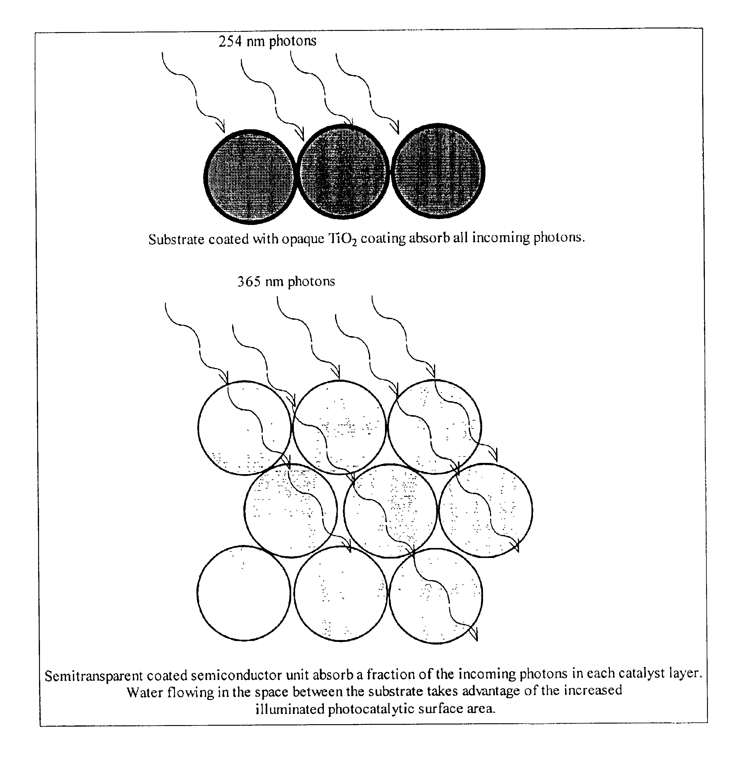
[0059]A semitransparent coating containing a zirconium oxide and brookite and anatase TiO2 was applied to a quartz slide using dip coating process. As shown in FIG. 6, there is significant transmission of light around 365 nm, the emission wavelength of typical “blacklight” UV sources. As the photon energy is increased, a successively larger fraction of the incident energy is absorbed by the semiconductor coating. For the current invention the rate of oxidation of organic compounds, under typical operating conditions, can be expressed as:

rate=kA((1−T)I)nΘorganic[moles or mass / time]  (1)

where:[0060]k=rate constant;[0061]A=irradiated surface area;[0062]T=fractional transmission of incident light through the photocatalytic layer;[0063]I=incident light intensity;[0064]Θ=surface concentration of organic compound; and,[0065]n=reaction order in light intensity—typically about 0.5.

For typical opaque photocatalytic coatings T is essentially zero and the reaction rate is simply proportional to...

example 3

[0069]Semiconductor photocatalyst coated glass spheres were made and tested. Brookite and anatase TiO2 plus ZrO2 was coated onto 6 mm soda-lime glass spheres. The transparency of each coating layer to 365 nm light was about 85%. A packed bed of these spheres were placed in a test cell of radius 2.2 cm. Air at 40% relative humidity was passed through the bed at a flow rate of 40 cm3 / s. Formaldehyde was used as the test contaminant at 2 ppm(v / v). The test cell was irradiated from above with a 365 nm UV source at 7.0 mW / cm2. The single pass conversion of formaldehyde was measured as a function of sphere depth.

[0070]The results of this experiment are summarized in Table 1. These results show that as more layers of spheres were added, increasing the bed depth, the single pass conversion of formaldehyde increased. Since the illumination of each successive coating decreases, the overall system volumetric performance decreases with increased bed depth as illustrated by the keffa / V (space ve...


PUM

PropertyMeasurementUnit
Fractionaaaaaaaaaa
Fractionaaaaaaaaaa
Thicknessaaaaaaaaaa

Abstract

An apparatus and method for the photocatalytic conversion of contaminants in a fluid stream. Fluid is directed through a semitransparent packed bed or an open cell, three dimensionally reticulated, fluid permeable, semiconductor unit. Within the unit, a semiconductor, when exposed to a photoactivating light source, converts the contaminants through a photocatalytic reaction. Both the substrate and the semiconductor photocatalyst are semitransparent to the activating light to allow penetration of light into the unit, thereby distributing the light, increasing the active specific surface area, and improving the net conversion performance of the unit.

Description

[0001]This application is a continuation-in-part of U.S. patent application Ser. No. 09 / 721,803, which was filed on Nov. 22, 2000, now U.S. Pat. No. 6,524,447, and which claims priority from U.S. Provisional Application Ser. No. 60 / 166,855, which was filed on Nov. 22, 1999.FIELD OF THE INVENTION[0002]The present invention generally relates to a method and apparatus for the purification and disinfection of fluids. More specifically, the present invention relates to an apparatus and method of use of a semitransparent semiconductor material for the photocatalytic conversion of contaminants in fluids. The present invention discloses an apparatus and method incorporating a packed bed or rigid, open cell, three dimensionally reticulated, fluid permeable, photocatalytic semiconductor unit that is partially transparent to ultraviolet radiation.BACKGROUND OF THE INVENTION[0003]Heterogeneous photocatalysis is the general term that describes the technical approach. Mills, A., Le Hunte, S., “An...

Claims


Application Information

Patent Timeline
IPC IPC(8): A61L2/08B01J19/30B01J19/24B01J19/12B01J35/00C02F9/00C02F1/72C02F1/32B01J23/42B01J21/06B01J21/00B01J37/00B01J37/02C02F1/30
CPCC02F9/005A61L2/088B01J19/123B01J19/127B01J19/2495B01J19/30B01J35/002B01J35/004C02F1/30C02F1/325C02F1/725C02F2103/04C02F2201/3222C02F2305/10B01J21/063B01J21/066B01J23/42B01J37/0215B01J2219/0209B01J2219/0254B01J2219/0277B01J2219/0286B01J2219/0877B01J2219/1943B01J2219/30433B01J2219/30475C02F2201/3221B33Y80/00C02F9/20
Inventor CARMIGNANI, GARYFREDERICK, LEESITKIEWITZ, STEVE
Owner FLUID LINES
Why Eureka
Try Eureka