Primarily niobium stent

a niobium stent and stent technology, applied in the field of stents, can solve the problems of acute blockage, new blockage of the treated vessel, tissue irritation can exacerbate restenosis, etc., and achieve the effect of improving structural performance, avoiding brittleness and thrombogenicity

Inactive Publication Date: 2006-09-05
BOSTON SCI SCIMED INC
View PDF152 Cites 62 Cited by
  • Summary
  • Abstract
  • Description
  • Claims
  • Application Information

AI Technical Summary

Benefits of technology

[0020]Applicant has found that a stent composed primarily of niobium alloyed with a trace amount (e.g., less than 5% by weight, preferably about 1%) of preferably zirconium, but alternatively tantalum or titanium, or additive material such as described in U.S. Pat. Nos. 5,472,794 and 5,679,815, exhibits considerably improved performance structurally, e.g., to avoid brittleness and thrombogenicity, if the completed stent is annealed post-fabrication in a substantially oxygen-free atmosphere. The latter should be an extreme vacuum environment of from 10−4 to 10−6 millibars (mbar) pressure, preferably 10−5 mbar or less vacuum pressure, with less than about 80 parts per million (ppm) of O2, at an annealing temperature exceeding 400° C., preferably about 1200° C., for several hours, nominally more than one hour. O2 and H2 content of the stent material should be kept at low levels.

Problems solved by technology

For a large segment of patients undergoing the procedure, traditional angioplasty has resulted in new blockage of the treated vessel only a relatively short time thereafter, attributable to trauma to the blood vessel wall from the original procedure.
The presence of the stent in the vessel, however, tends to promote thrombus formation as blood flows through the vessel, which results in an acute blockage.
At the outward facing surface of the stent in contact or engagement with the inner lining of the vessel, tissue irritation can exacerbate restenosis attributable to hyperplasia.
This relatively thin and tiny metal structure creates little shadow on a fluoroscopic picture, however, since the x-ray absorption of the metal is low.
Increasing the wall thickness of the stent to enhance its radiopacity and recoil resistance makes the stent less flexible, however, which adversely affects its maneuverability through narrow vessels and the amount of balloon pressurization necessary to enlarge the stent diameter sufficiently during deployment, with concomitant increased risk of balloon rupture.
Despite improvements in the design and construction of coronary stents, restenosis remains a problem.
A major contributing factor is the inability of the body to incorporate the implanted foreign material quickly.
It has been an assumption among industry practitioners and researchers that a highly polished and smooth surface is beneficial to prevent stent thrombosis and to facilitate endothelialization, but experiments indicate this may not be entirely true.
But the fluoroscopic visibility of stainless steel, for example, in a thickness below 60 μm is very poor because of the limited extinction of x-rays by such a thin metal tube.
Coatings, however, present a need for absolute adherence to the underlying metal of the stent to avoid cracking or defects in the homogeneous overlying layer, and sufficient resistance to peeling or flaking of the layer during insertion, and especially during expansion of the diameter of the stent as it is being deployed in final position in the artery at the target site, objectives which are not easily achievable.
The disadvantage of reduced mechanical strength of noble metals such as gold or platinum—which makes them unsuitable if sought to be used alone for application in the human vascular system—is overcome by the use of a core composed of a material such as stainless steel, having considerably better mechanical properties than the noble metal.
But the presence of cracks or related defects in the surface coating can produce a galvanic potential which could ultimately lead to corrosion of the underlying steel or lesser metal, an unacceptable situation for a device intended to be permanently implanted in the body.
Therefore, manufacturing requires a high degree of quality control and concomitant high cost.

Method used


Image

  • Primarily niobium stent
  • Primarily niobium stent

Examples


Embodiment Construction

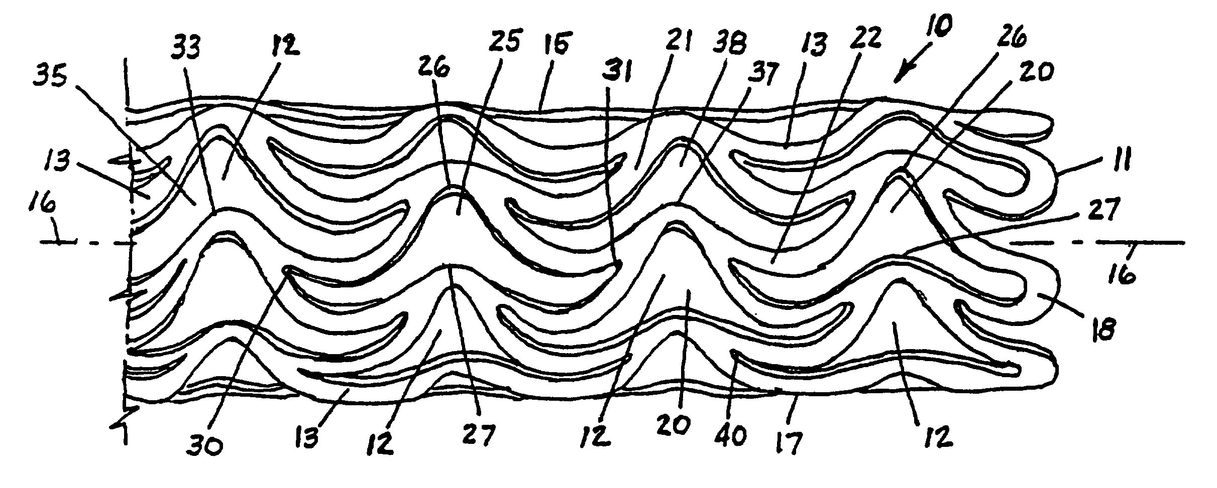
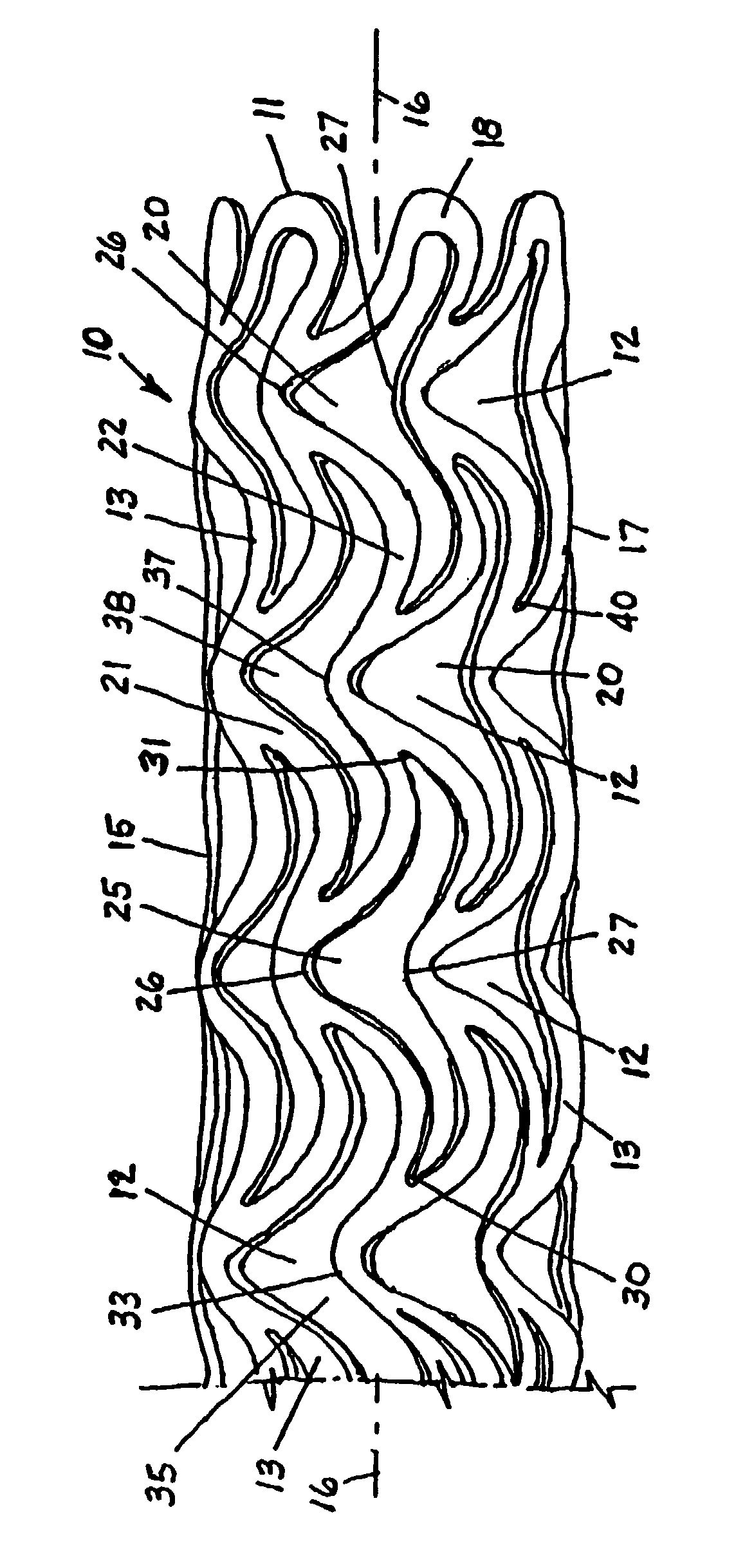
[0023]The sole FIGURE is a perspective view (not to scale) of a stent 10 in the form of a hollow tubular self-supporting structure composed primarily of niobium (Nb), with a trace amount of zirconium (Zr), titanium (Ti) or tantalum (Ta) for example, preferably zirconium, the trace amount preferably less than 5%, more preferably approximately 1%, and remainder niobium. The added trace metal improves physical characteristics of the stent for its intended function. Typically, the stent material used by applicant also has negligible amounts of tantalum (Ta, about 180 micrograms per gram (μg / g)), iron (Fe, <20 μg / g), silicon (Si, about <μg / g), tungsten (W, <20 μg / g), nickel (Ni, <20 μg / g), molybdenum (Mo, <20 μg / g), hafnium (Hf, <20 μg / g), carbon (C, about 7 μg / g), and nitrogen (N, about 53 μg / g), as well as amounts of hydrogen (H) and oxygen (O) primarily introduced during the processing.

[0024]Important values of these minor elemental constituents are those of O2 and H2. Both of these e...


PUM

PropertyMeasurementUnit
thicknessesaaaaaaaaaa
diameteraaaaaaaaaa
thicknessaaaaaaaaaa

Abstract

In a process of fabricating a stent composed primarily of niobium alloyed with a trace amount of zirconium, tantalum, or titanium for hardening, the stent is annealed under vacuum in a substantially oxygen-free environment. The vacuum is preferably maintained at pressure less than 10−4 millibars, oxygen-content less than about 80 parts per million, and the annealing temperature exceeds 400° C. for at least one hour, and is preferably kept in a range from about 1100–1200° C. for several hours. This may be followed by applying a surface layer of oxide, such as iridium oxide, with a thickness of 299–300 nm to the stent.

Description

CROSS-REFERENCE TO RELATED APPLICATIONS[0001]This application is a continuation-in-part of U.S. patent application Ser. No. 09 / 663,896, filed Sep. 18, 2000 (“the '896 application”) now issued as U.S. Pat. No. 6,478,815, and is further related to U.S. patent application Ser. No. 09 / 634,667 now issued as U.S. Pat. No. 6,387,121, filed Aug. 8, 2000 (“the '667 application”), both of the same assignee as the present application.BACKGROUND OF THE INVENTION[0002]The present invention relates generally to stents that are implantable or deployable in a vessel or duct within the body of a patient to maintain the lumen of the duct or vessel open, and more particularly to improvements in stent structures.[0003]When inserted and deployed in a vessel, duct or tract of the body, for example a coronary artery after dilatation of the artery by balloon angioplasty, a stent acts as a prosthesis to maintain the vessel, duct or tract (generally referred to as a vessel for convenience herein) open. The s...

Claims


Application Information

Patent Timeline
Patent Type & Authority Patents(United States)
IPC IPC(8): A61F2/06A61F2/00A61F2/84A61L31/00A61F2/90A61L31/02A61L31/08A61L31/18C22C27/02C22F1/00C22F1/02C22F1/18
CPCA61F2/91A61F2/915A61L31/18A61L31/022A61L31/088A61F2002/91541A61F2310/00598A61F2002/91558
Inventor SCHEUERMANN, TORSTENALT, ECKHARD
Owner BOSTON SCI SCIMED INC
Why Eureka
Try Eureka