
Powdered metal inlay

a technology of powdered metal and inlay, which is applied in the field of powdered metal inlay, can solve the problems of premature valve failure, high pressure and repetitive impact load on the valve body and valve seat, and high pressure on the valve seat, and achieves high density, high repeatability, and preservation of hardness and wear resistan

Inactive Publication Date: 2010-06-01
NOVATECH HLDG CORP
View PDF19 Cites 42 Cited by
  • Summary
  • Abstract
  • Description
  • Claims
  • Application Information

AI Technical Summary

Benefits of technology

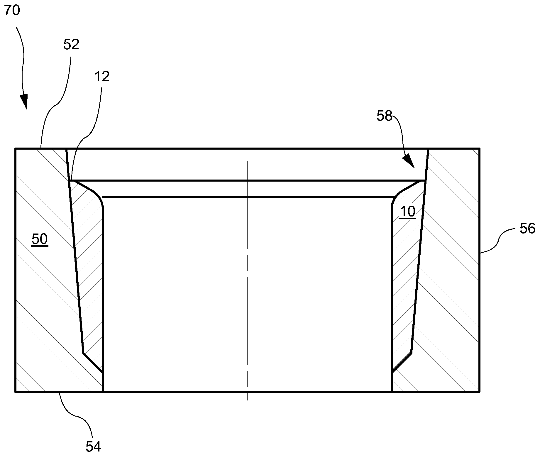
[0038]In making a valve seat as described above, a tapered interface between inlay and hull rings comprising similarly-tapered frusto-conical bonding surfaces provides a additional advantages beyond the self-centering function. Because the tapered interface converts a portion of valve body impact force to a force component normal to the interface, the shear component of valve body impact force acting on the interface is reduced. This reduces stress on the inlay-ring-hull-ring fusion bond. Further, the wedging action of the similarly-tapered frusto-conical bonding surfaces under the valve body impact force tends to effectively transmit the force via the hull to one or more peripheral flanges where it can be absorbed without damage.
[0045]Note that in sealingly vacuum brazing an inlay ring and a hull ring as described herein, a vacuum of about 0.1 torr or better must be created in the brazing furnace to ensure sufficiently high density in the valve seat inlay that is formed during subsequent HIPPING. Note also that brazing with a filler metal comprising, for example, nickel (e.g., BNi-5 or alloys associated with the registered trademarks Colmonoy and Nicrobraz) will tend to protect the sintered carbide particles from loss of carbon (decarburization), thus tending to preserve their hardness and wear-resistance. Certain of these brazing materials can be sprayed on surfaces to be brazed, thus facilitating quality control measures to ensure uniform and highly repeatable results. Note further that frusto-conical surface half-angles are conveniently represented and measured using phantom extensions of the relevant surface which intersect the relevant longitudinal axis, and / or measuring or indicating with respect to one or more phantom lines parallel to the relevant longitudinal axis.

Problems solved by technology

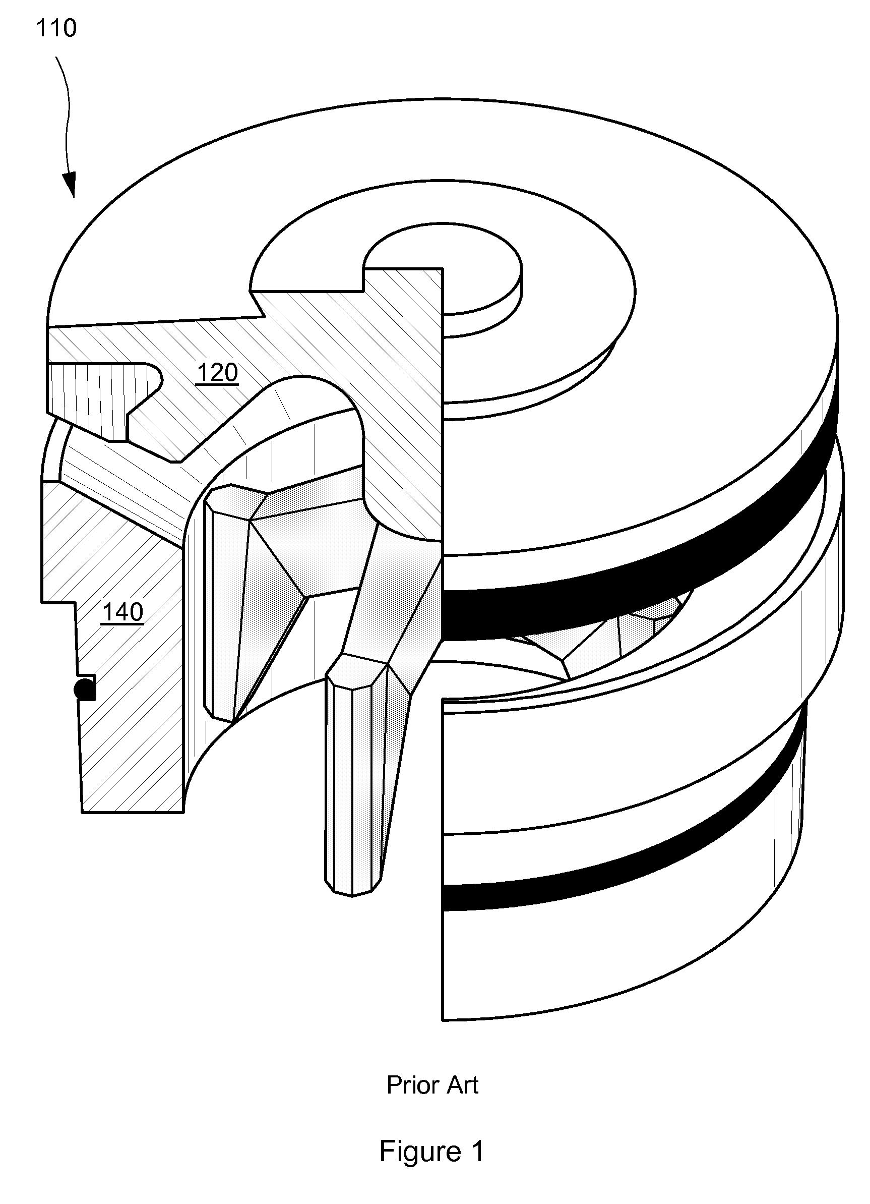
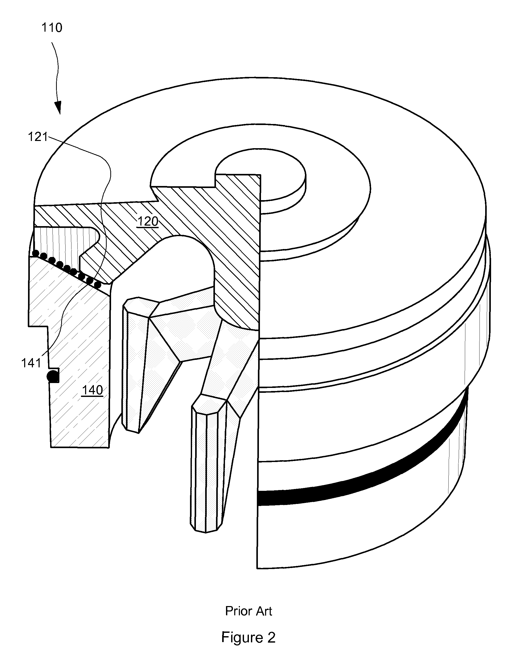
Such valves typically experience high pressures and repetitive impact loading of the valve body and valve seat.
These severe operating conditions have in the past often resulted in leakage and / or premature valve failure due to metal wear and fatigue.
Valve sealing surfaces are subject to exceptionally harsh conditions in exploring and drilling for oil and gas, as well as in their production.
During fracturing, cracks are created in the rock of an oil bearing formation by application of high hydraulic pressure.
Unfortunately, both sand and aluminum oxide slurries are very abrasive, typically causing rapid wear of many component parts in the positive displacement plunger pumps through which they flow.
Accelerated wear is particularly noticeable in plunger seals and in the suction (i.e., intake) and discharge valves of these pumps.
When back pressure begins to act on a valve, slurry particles become trapped in the narrow space that still separates the sealing surfaces of the valve body and seat.
Swiftly rising back pressure tends to drive slurry backwards through the now-sealed valve, but since back-flow is blocked by the initial valve sealing, pressure builds rapidly on the entire valve body.
Any crushed slurry particles previously trapped between the sealing surfaces are then ground against these surfaces, resulting in extreme abrasive action.
But if certain portions of the object are cooled at rates different from those applicable to other portions of the object, then the crystal lattice structure of the cooled object may be non-uniform.
Further, if steel is heated too far above its upper transformation temperature before quenching, its grain structure may be unnecessarily coarsened, meaning that the steel will then be less tough and more brittle after quenching than it would have been if its maximum temperature had been closer to its upper transformation temperature.
Certain tool steels may even be quenched by gas (e.g., air or inert gas), but the carbon steels traditionally used for valve seats can not be gas-quenched if they are to develop the hardness, strength and toughness necessary for use in high-pressure valves.
But preferred heat treatments are highly specific to particular alloys, so there may be no single optimal heat treatment for a component such as a valve seat comprising, for example, a high-alloy sealing surface inlay on a carbon steel substrate.
Indeed, even the most careful use of heat treatments to favor development of hard sealing surfaces on strong, tough substrates has not proven effective for extending the service life of valves traditionally used for high-pressure abrasive slurries.
But such carbides do not bond well with the low-carbon steels commonly used in high pressure valve seats.
A cement (comprising, e.g., cobalt, chromium, and / or nickel) is then added to the crushed carbide powders, but there is little or no opportunity for the cement to alloy with the carbides.
The resulting cemented carbide inlays are thus not homogeneous, so they do not possess the uniform hardness that would ideally be desired for good abrasion resistance and toughness in valve sealing surfaces.
One problem associated with this inhomogeneity becomes evident because the crushing and grinding of slurry particles between valve sealing surfaces during valve closure produces a variety of slurry particle sizes, some so fine that they are smaller than the spacing between the carbide particles in the cemented carbide inlay.
These fine slurry particles are very abrasive, and if they can fit between the carbide particles they can rapidly wear away the relatively soft cement holding the carbide particles in place.
Thus loosened (but not actually worn down), the carbide particles can simply be carried away by the slurry stream, leaving the remainder of the inlay cement exposed to further damage by the abrasive slurry.
But weld-applied carbide inlays have not been found acceptable in high pressure valves.
This is due in part to a need for relatively high cement content in weld-applied inlays, leading to relatively high porosity inlays having low abrasion resistance and a predisposition to multiple internal stress risers.
The result has typically been an increased likelihood of premature (often catastrophic) valve failures.
While such cracks are tolerated in certain applications where the cracks do not significantly affect the performance of the part, the same can not be said of high pressure valves.
On the contrary, cyclic fatigue associated with the repeated large impact loads experienced by these valves magnifies the deleterious effects of cracks and residual stresses that may result from differentials in coefficients of thermal expansion.
Premature catastrophic failures of valve bodies and / or seats are a frequent result.
Notwithstanding the high grade and high cost of the tool steel cladding however, these experimental valve seats have not been successful because the reheat treatment required to reduce the cladding's brittleness does not simultaneously cause development of the required strength and toughness in the low-carbon steel substrate.
Of course, the substrate could be eliminated if P / M powder were used to form an entire structure such as a valve seat by use of HIP (i.e., by HIPPING), but the cost of a valve seat comprising 100% of P / M grade tool steels would be prohibitive.
And in spite of its high cost, such a valve seat would lack the toughness and strength otherwise obtainable if mild steel or a lower grade tool steel were used as a substrate.
Even when welded ideally, a P / M inlay will lose its fine microstructure in the weld fuse zone, where it melts during welding.
Thus, P / M grades, when welded, do not achieve optimal toughness.
Further, the melting that occurs during welding will decarburize some of the carbides, decreasing wear resistance.
For these reasons, using welding to apply the high alloy P / M grades on heavy impact areas such as a valve seat will always present some risk of cracking in service.
Such porous defects, if present under cyclic fatigue impact loading, act as stress risers which lead to cracks, crack propagation, and catastrophic failure.
A sintered preform will generally be more likely to retain its shape during handling than a presintered preform, but sintering also encourages metallic grain growth that is associated with preform brittleness.
Note that the currently practices of various versions of the basic CIP process described above are all relatively expensive.
High costs are associated with the molds and the tooling for the upper and lower portions of the can assembly, as well as the special handling required in welding, pressure testing, evacuating, crimping, and sealing can assemblies.
In fact, the cost of preparing evacuated can assemblies as described above may substantially exceed the cost of applying HIP to these same assemblies.

Method used


Image

  • Powdered metal inlay
  • Powdered metal inlay
  • Powdered metal inlay

Examples


first embodiment

[0059]FIG. 8 schematically shows a first embodiment valve seat 70′ comprising an inlay ring 10′ (analogous-in-part to inlay ring 10) and a hull ring 50′ (analogous-in-part to hull ring 50). Valve seat 70′ is obtained after the inlay ring and hull ring of assembly 70 are sealingly vacuum brazed together (with a filler metal) and then HIPPED (i.e., exposed to HIP), followed by finish machining. Due to its relatively high modulus of elasticity (compared to the hull ring modulus of elasticity), inlay ring 10′ substantially retains the initial predetermined shape to which inlay ring 10 was ground. And due to its relatively lower modulus of elasticity, hull ring 50 would be relatively more affected (e.g., distorted) by HIP than inlay ring 10. Thus, the finish machining required after HIPPING to make valve seat 70′ produces a hull ring configuration 50′ which differs from the shape of hull ring 50. Adding to such differences in shape are features (comprising, for example, peripheral flange...

fifth embodiment

[0061]the invention comprises a method of making an inlay on a metal substrate (see, e.g., valve seat 70′ in FIG. 8), the method comprising providing a metal substrate (see, e.g., hull ring 50 in FIG. 6) having a substrate modulus of elasticity. The method then comprises providing a compressed powdered metal inlay (see, e.g., inlay ring 10 in FIG. 5) comprising at least one metal carbide and at least one nonvolatile cement. The method then comprises sintering the compressed powdered metal inlay and grinding to an initial predetermined shape to make an inlay preform, the inlay preform having a preform modulus of elasticity substantially greater than the substrate modulus of elasticity. The method then comprises sealingly vacuum brazing the inlay preform to the metal substrate to make an evacuated assembly having at least one evacuated bonding area between the inlay preform and the metal substrate. And the method finally comprises applying hot-isostatic-pressure to the evacuated assem...


PUM

PropertyMeasurementUnit
back pressureaaaaaaaaaa
pressureaaaaaaaaaa
porosityaaaaaaaaaa

Abstract

Hot-isostatic-pressure (HIP) is used to bond a cemented carbide inlay (e.g., an inlay ring) on a metal substrate (e.g., a hull ring). For example, an inlay ring is made from a powdered metal inlay preform typically comprising at least one metal carbide and at least one nonvolatile cement. The inlay preform is compressed and sintered to make an inlay ring having a predetermined shape, the inlay ring having a modulus of elasticity substantially greater than that of a hull ring. An inlay ring and a hull ring are sealingly vacuum brazed together with at least one evacuated bonding area between them. HIP is applied to compress the hull ring against the inlay ring, thus fusing the hull ring and inlay ring in at least one evacuated bonding area. Following HIP, the inlay ring and hull ring form a fused assembly in which the inlay ring substantially retains its predetermined shape.

Description

[0001]This application is a continuation-in-part of copending U.S. Ser. No. 11 / 382,298 filed 9 May 2006.FIELD OF THE INVENTION[0002]The invention relates generally to inlays comprising one or more metal carbides on metal substrates.BACKGROUND[0003]Valve terminology varies according to the industry (e.g., pipeline or oil field service) in which the valve is used. In some applications, the term “valve” means just the valve body, which reversibly seals against the valve seat. In other applications, the term “valve” includes components in addition to the valve body, such as the valve seat and the housing that contains the valve body and valve seat. A valve as described herein comprises a valve body and a corresponding valve seat, the valve body typically incorporating an elastomeric seal within a peripheral seal retention groove.[0004]Valves can be mounted in the fluid end of a high-pressure pump incorporating positive displacement pistons or plungers in multiple cylinders. Such valves ...

Claims


Application Information

Patent Timeline
Patent Type & Authority Patents(United States)
IPC IPC(8): F16K51/00
CPCF04B53/102F04B53/1082F16K1/465F16K31/041F04B53/1087Y10T29/49421B22F5/008B22F5/106B22F7/08B22F2998/10B22F2999/00C22C29/06C22C29/08F16K15/06C22C1/051B22F3/04B22F3/10B22F3/15B22F2207/20B22F7/064
Inventor BLUME, GEORGE H.
Owner NOVATECH HLDG CORP
Learn More