
Fluorescent substance and process for producing the same, and luminescent element using the same

a fluorescence substance and luminescent element technology, applied in the field of white led, can solve the problems of inability to obtain phosphor powder of nitride phosphor or oxynitride phosphor with satisfactory properties, increased chance of incorporation of impurities, and introduction of defects into the surface of each particle, etc., to achieve excellent luminescence properties, high energy efficiency, and superior fluorescence properties

Active Publication Date: 2012-02-28
DENKA CO LTD
View PDF37 Cites 14 Cited by
  • Summary
  • Abstract
  • Description
  • Claims
  • Application Information

AI Technical Summary

Benefits of technology

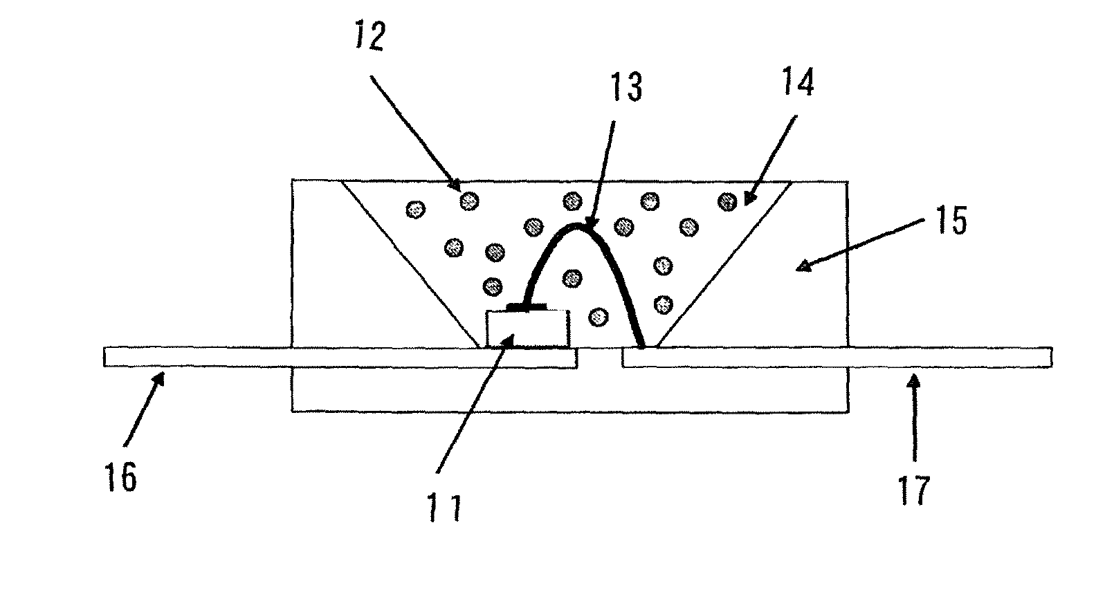
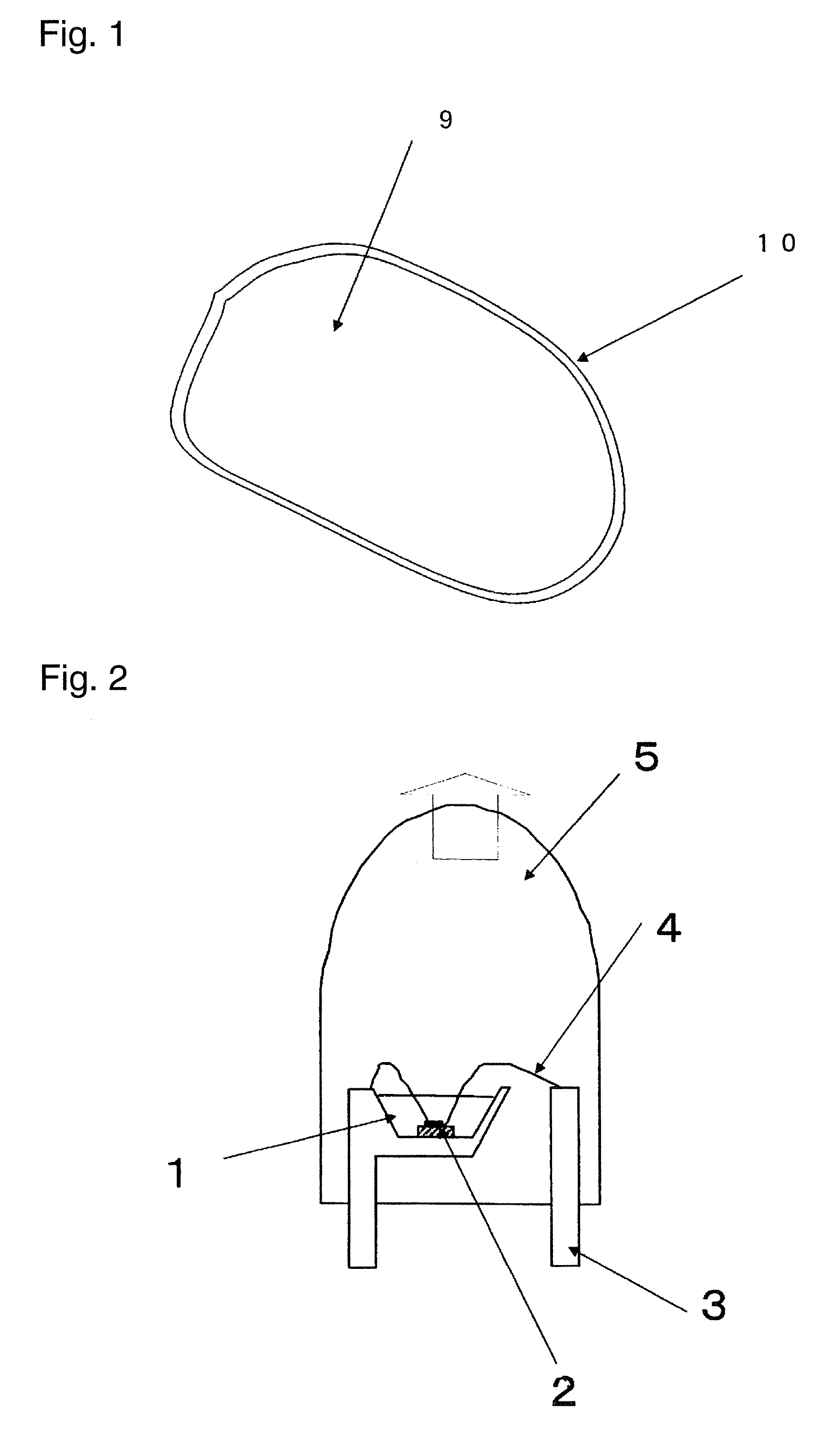
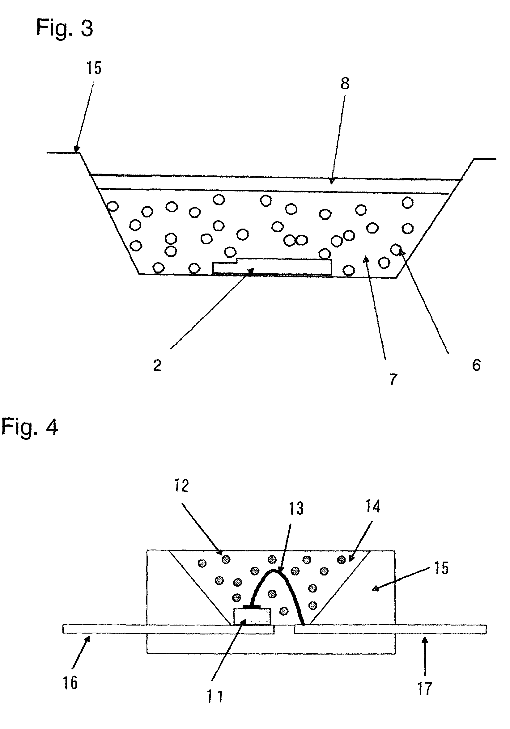
The present invention provides a new powdery phosphor with improved luminous efficiency, particularly for use in white LEDs. The phosphor is made by combining specific elements in a nitride or oxynitride structure, with a transparent film formed on the surface of each particle. The phosphor has a unique structure that allows for better dispersion in resin and improved luminescence properties compared to conventional phosphors. The invention also addresses the issue of surface coating and provides a method for achieving a uniform coating. The present invention solves the problem of impurities and variations in color caused by surface oxidation. Overall, the invention provides a new phosphor with improved properties for use in LEDs.

Problems solved by technology

As described above, the conventional techniques had the problem that the powder of the nitride phosphor or oxynitride phosphor could not be obtained as a phosphor powder with a satisfactory property, by simply mixing and heating nitrides containing constituent elements and a compound containing an activating element or by simply reduction-nitriding a mixture of oxides of constituent elements in the presence of carbon or the like.
As the pulverization conditions become severer, a chance of incorporation of impurities becomes larger and a defect is introduced into a surface of each particle.
The phosphor is excited in the vicinity of its surface with excitation light to emit fluorescent light, and the surface defects introduced by the pulverization treatment significantly affect the fluorescence property and raised the problem of degradation of the luminescence property.
Furthermore, the nitride powder contains oxygen as an unavoidable impurity and there are two types of oxygen; oxygen existing in the form of a solid solution in the particles and oxygen existing in the form of oxide coating films on surfaces of the particles.

Method used


Image

  • Fluorescent substance and process for producing the same, and luminescent element using the same
  • Fluorescent substance and process for producing the same, and luminescent element using the same
  • Fluorescent substance and process for producing the same, and luminescent element using the same

Examples


example 1

Example 1-1

[0141]An α-sialon of this example had a composition of raw-material powders composed of 83.0 parts by mass of a silicon nitride powder (manufactured by Denki Kagaku Kogyo Kabushiki Kaisha, 9FW grade), 10.5 parts by mass of an aluminum nitride powder (manufactured by Tokuyama Corporation, F grade), 1.5 parts by mass of a europium oxide powder (manufactured by Shin-Etsu Chemical Co., Ltd., RU grade) and 5.5 parts by mass of a calcium sulfide powder (manufactured by Wako Pure Chemical Industries, Ltd.).

[0142]Then the above raw-material powders were mixed by a wet ball mill with a silicon nitride pot and balls in an ethanol solvent for three hours, and filtered and dried to obtain a powder mixture. An amount of oxygen in the powder mixture was measured by an oxygen analyzer manufactured by LECO Corporation and it was 1.2 mass %. 100 g of the powder mixture was filled in a boron nitride crucible with an inner diameter of 100 mm and a height of 60 mm, and subjected to a heat tr...

example 1-2

[0145]An α-sialon phosphor was produced in the same manner as in Example 1-1 except that 2.8 parts by mass of a calcium sulfide powder and 3.8 parts by mass of a calcium carbonate (hereinafter also referred to simply as “CaCO3”) powder (manufactured by KANTO CHEMICAL CO., INC., a guaranteed reagent) were used instead of 5.5 parts by mass of a calcium sulfide (hereinafter also referred to simply as “CaS”) in the raw-material powders of Example 1-1. In this case, the molar ratio of CaS / CaCO3 is 1. An amount of oxygen in the powder mixture of the raw-materials was 3.4 mass %.

[0146]A composition of the α-sialon thus obtained was Ca0.48Eu0.05Si10.4Al1.6O0.5N15.5, wherein X+Y=0.53 and Y / (X+Y)=0.09. An amount of oxygen calculated based on the compositional formula was 1.36 mass%. An amount of oxygen in the α-sialon phosphor obtained was measured with the oxygen analyzer manufactured by LECO Corporation and it was 1.71 mass%. Furthermore, a fluorescence property was measured in the same man...

example 1-3

[0149]The α-sialon phosphor obtained in Example 1-2 was dispersed in a solution mixture of 48% hydrofluoric acid:60% nitric acid:distilled water=40:10:50 (vol %), maintained at 50° C. for 2 hours, washed and filtered with distilled water, further dispersed in a solution mixture of concentrated sulfuric acid:distilled water=50:50 (vol %), maintained at 90° C. for 2 hours, washed and filtered with distilled water, and dried. An amount of oxygen in the powder obtained was 1.55 mass %. A relative value of the luminescence intensity was 90.


PUM

PropertyMeasurementUnit
thicknessaaaaaaaaaa
refractive indexaaaaaaaaaa

Abstract

Provided is a phosphor material for a white LED with a blue LED or ultraviolet LED as a light source.A phosphor comprises an α-sialon represented by the formula: (M1)X(M2)Y(Si)12−(m+n)(Al)m+n(O)n(N)16−n where M1 is at least one element selected from the group consisting of Li, Mg, Ca, Y and lanthanide metals (except for La and Ce), M2 is at least one element selected from Ce, Pr, Eu, Tb, Yb and Er, 0.3≦X+Y≦1.5, 0<Y≦0.7, 0.6≦m≦3.0, 0≦n≦1.5 and X+Y=m / 2; and the oxygen content in a powder of the α-sialon is at most 0.4 mass % larger than a value calculated based on the formula.

Description

TECHNICAL FIELD[0001]The present invention relates to an α-sialon phosphor excited by ultraviolet to blue light to emit visible light, a process for its production, and a light emitting device using it, particularly a white LED.BACKGROUND ART[0002]Phosphors widely known are those using a silicate, a phosphate, an aluminate or a sulfide as a matrix material and a transition metal or a rare earth metal as a luminescent center. On the other hand, with respect to a white LED, attention is drawing toward phosphors excited by an excitation source with high energy such as ultraviolet or blue light to emit visible light, and development thereof is under way. However, the above-mentioned conventional phosphors have a problem that the luminance thereof decreases as a result of exposure to the excitation source. Recently, nitride and oxynitride phosphors are drawing attention as phosphors with small decrease in luminance, because they are materials having a stable crystal structure and being c...

Claims


Application Information

Patent Timeline
Patent Type & Authority Patents(United States)
IPC IPC(8): C09K11/00C09K11/59H01L33/50
CPCB82Y30/00C04B35/62675C04B35/6281C04B35/62813C04B35/62884C04B35/62892C04B35/62897C09K11/7734C04B35/597Y10T428/2993C04B2235/3203C04B2235/3206C04B2235/3208C04B2235/3224C04B2235/3225C04B2235/3229C04B2235/3409C04B2235/3865C04B2235/3869C04B2235/3873C04B2235/3895C04B2235/441C04B2235/442C04B2235/445C04B2235/446C04B2235/5296C04B2235/5436C04B2235/5454C04B2235/549C04B2235/72C04B2235/724C04B2235/766C04B2235/767C04B2235/79H01L33/502H01L2924/181H01L2224/32245H01L2224/48091H01L2224/48247H01L2224/48257H01L2224/73265C09K11/77348H01L2924/00014H01L2924/00012H01L2924/00
Inventor EMOTO, HIDEYUKIIBUKIYAMA, MASAHIRONOMURA, KENJI
Owner DENKA CO LTD
Learn More