
Micro and nanoscale magnetoelectric multiferroic lead iron tantalate-lead zirconate titanate

Active Publication Date: 2016-03-29
UNIVERSITY OF PUERTO RICO
View PDF5 Cites 4 Cited by
  • Summary
  • Abstract
  • Description
  • Claims
  • Application Information

AI Technical Summary

Benefits of technology

The present invention provides a new type of material that has properties of a magnet and a electric component in one substance. The material can be made in both ceramic and thin film forms, and has high dielectric constant, low dielectric loss, and can be controlled with electricity. It can also change its magnetic properties with electricity. The material can be used to create room temperature devices that have both magnetic and electric properties.

Problems solved by technology

In case of multiferroic terbium manganites TbMnO3 or TbMn2O3, the inconvenience for practical applications is their weak ferroelectric properties at very low temperature (<40 K).
However, in perovskite oxide structure family, one of the promising Bi compound is BiFeO3 (BFO), which has multiferroic behavior at room temperature, with a remanent polarization ˜50-60 μC / cm2, but it exhibits a weak ferromagnetism (1μB per unit cell), which makes the cross coupling among these ferroic parameters very weak and also poorly understood.
Additional problems with BFO are high leakage current, a tendency to fatigue, and thermal decomposition near the coercive field.

Method used


Image

  • Micro and nanoscale magnetoelectric multiferroic lead iron tantalate-lead zirconate titanate
  • Micro and nanoscale magnetoelectric multiferroic lead iron tantalate-lead zirconate titanate
  • Micro and nanoscale magnetoelectric multiferroic lead iron tantalate-lead zirconate titanate

Examples


example 1

Preparation and Properties of the Ceramic (PbZr0.53Ti0.47O3)(1-x)—(PbFe0.5Ta0.5O3)x (0.1≦x≦0.9) by Solid State Route

Materials and Methods

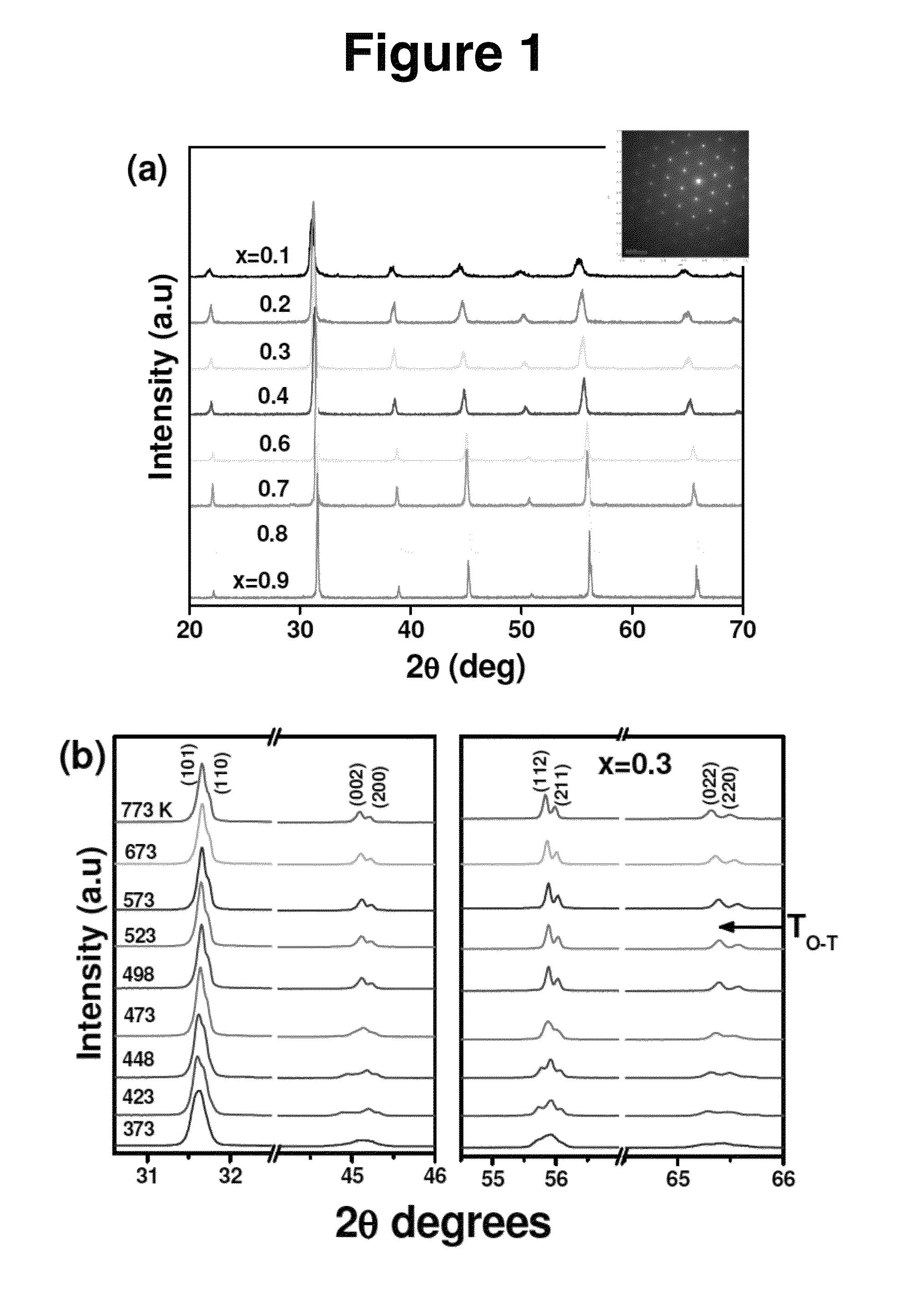
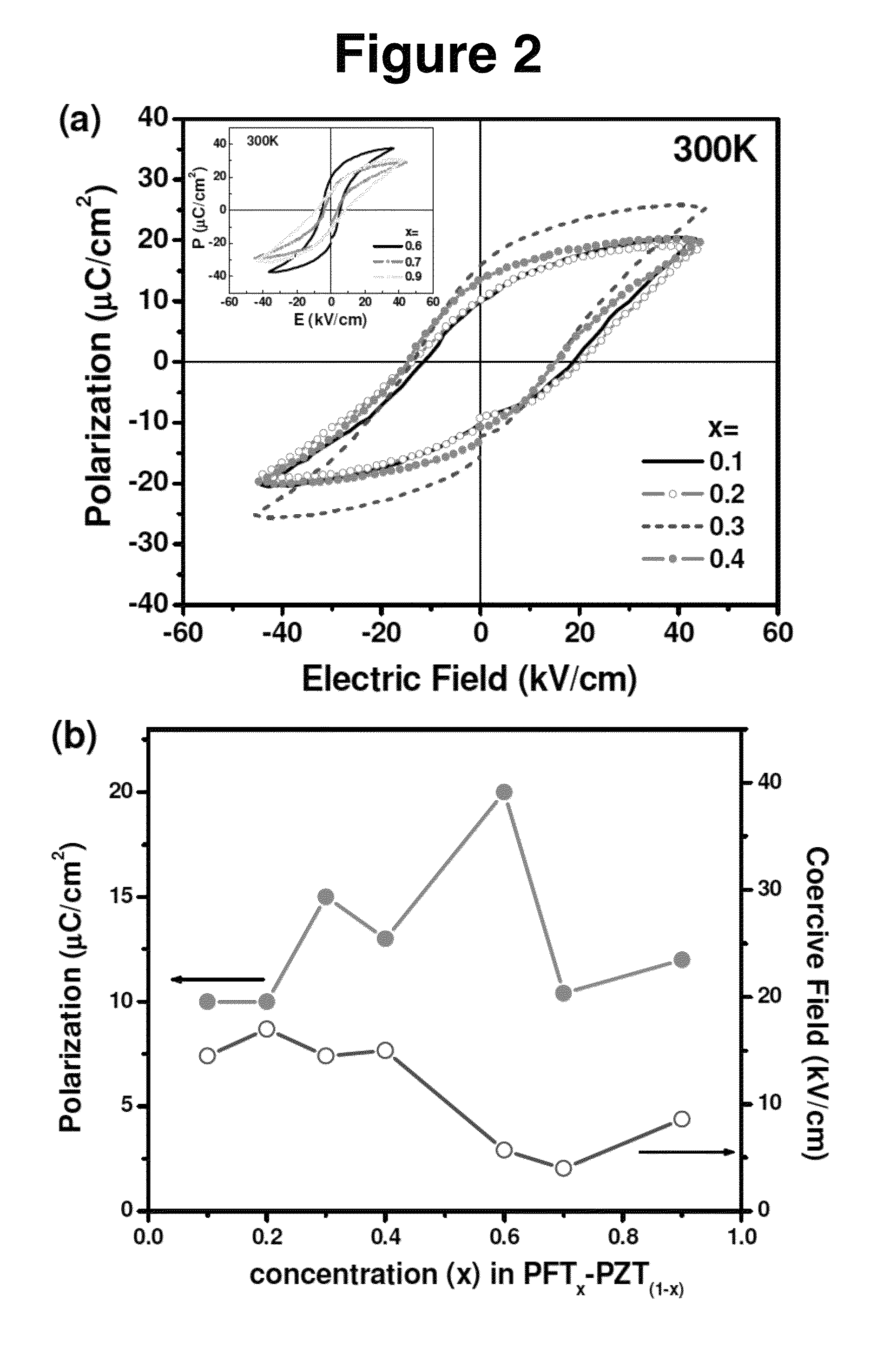
[0039]Magnetoelectric multiferroic (PbZr0.53Ti0.47O3)(1-x)—(PbFe0.5Ta0.5O3)x (0.1≦x≦0.9) ceramic samples were prepared by a solid-state route. Analytical-purity oxides, PbO (99.5%), ZrO2 (99.86%), TiO2 (99.96%), Fe2O3 (99.99%) and Ta2O5 (97%) (Alfa Aesar) were used as raw materials. The powder of the respective metal oxides were mixed in planetary high energy ball mill with tungsten carbide media at a ball-to-powder weigh ratio of 1:3, at a speed of 600 rpm for a period of 16 h, and then it was calcined at 1123 K for 10 h in a closed alumina crucible. 10% excess of PbO was added to each composition to compensate Pb deficiency during the high temperature processing. Poly (vinyl alcohol) solutions (1%) were added to the calcined powders as a binder. The dried powders were granulated by passing them through a 150 μm-mesh sieve and pressed using a hydr...

example 2

Preparation and Properties of (PbZr0.53Ti0.47O3)(1-x)—(PbFe0.5Ta0.5O3)x Thin Films by Pulsed Laser Deposition

Materials and Methods

[0057]Ceramic targets of (PbZr0.53Ti0.47O3)(1-x)—(PbFe0.5Ta0.5O3)x (0.1≦x≦0.9) with 10% excess of lead oxide (to compensate the loss of Pb due its volatility) were synthesized by a conventional solid-state route. Four different compositions of PZTFT (0.1≦x≦0.4) films were fabricated on conducting (bottom electrode for all electrical measurements) La0.67Sr0.33CoO (LSCO) coated (100) MgO substrate by pulsed laser deposition technique using a excimer laser (KrF, λ=248 nm). The conducting LSCO layer was grown on MgO substrate at 873 K under an oxygen pressure of 300 mT, using a laser energy density of 1.8 J / cm2 and repetition rate of 10 Hz, followed by normal cooling in oxygen atmosphere (300 Torr). The PZTFT layer was then deposited on the LSCO layer at 873 K under an oxygen pressure of 200 mTorr, using a laser energy density of (1.5 J / cm2) and repetition ra...


PUM

PropertyMeasurementUnit
Temperatureaaaaaaaaaa
Timeaaaaaaaaaa

Abstract

The invention is a novel class of materials made by combining the best qualities of both lead iron tantalate (PFT) and lead iron titanate (PZT) to synthesize (PbZr0.53Ti0.47O3)(1-x)—(PbFe0.5Ta0.5O3)x (PZTFT) (0.1≦x≦0.9) compositions that have multiferroic (ferroelectric and ferromagnetic) and magnetoelectric properties.

Description

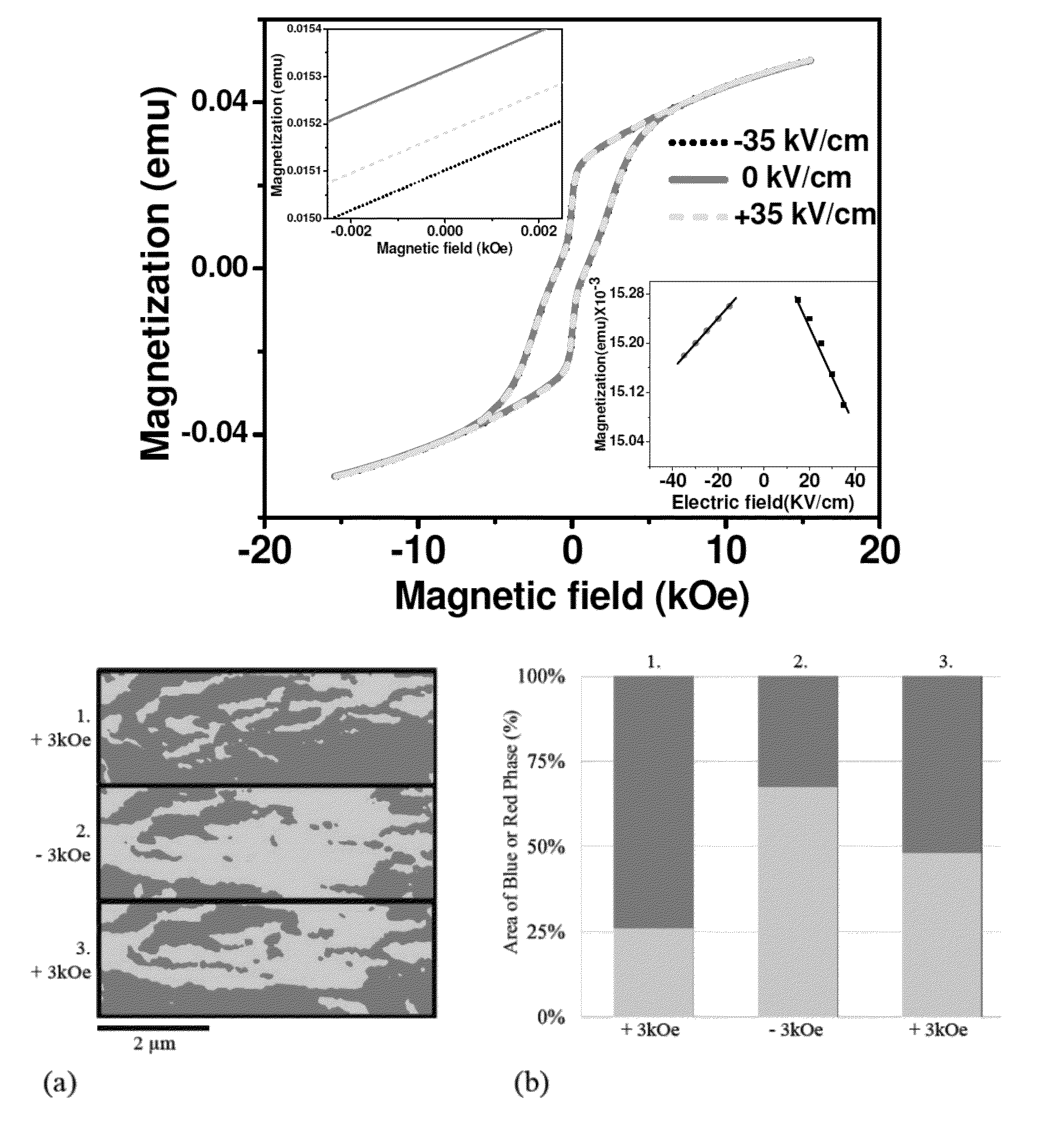
BACKGROUND OF THE INVENTION[0001]The anticipated end of Moore's law scaling in microelectronics has stimulated researchers to explore other alternatives i.e. to render the individual components to be multifunctional. One of the promising field in which the researchers have focused in order to explore the multifunctionality of the materials is Magnetoelectric (ME) multiferroics.[0002](ME) multiferroics are materials which possess simultaneously ferroelectric (FE) and ferromagnetic (FM) properties in the same phase and have coupling between them, that is, the switching of magnetization by electric field or polarization by magnetic field; have had a tremendous research interest due to a number of potential multifunctional applications in modern technologies, like sensor applications and random access memory devices. These ME materials have all the potential applications of their parent FE and FM materials; in addition to having a bifunctional property not available in systems with a si...

Claims


Application Information

Patent Timeline
IPC IPC(8): G11C11/00C23C14/18H01F1/03G11C11/16
CPCH01F1/0315G11C11/1673G11C11/1675C23C14/18G11C11/15G11C11/22C23C14/088C23C14/28H01F1/407
Inventor KATIYAR, RAM, SKUMAR, ASHOKORTEGA, NORA, PATRICIASANCHEZ, DILSOM, ALBERTOSCOTT, JAMES, FLOYDEVANS, DONALD, MALCOLMGREGG, JOHN, MARTIN
Owner UNIVERSITY OF PUERTO RICO
Learn More