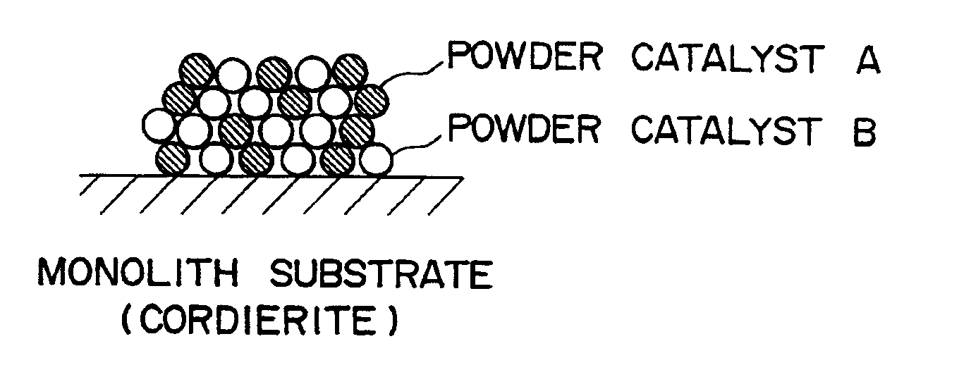
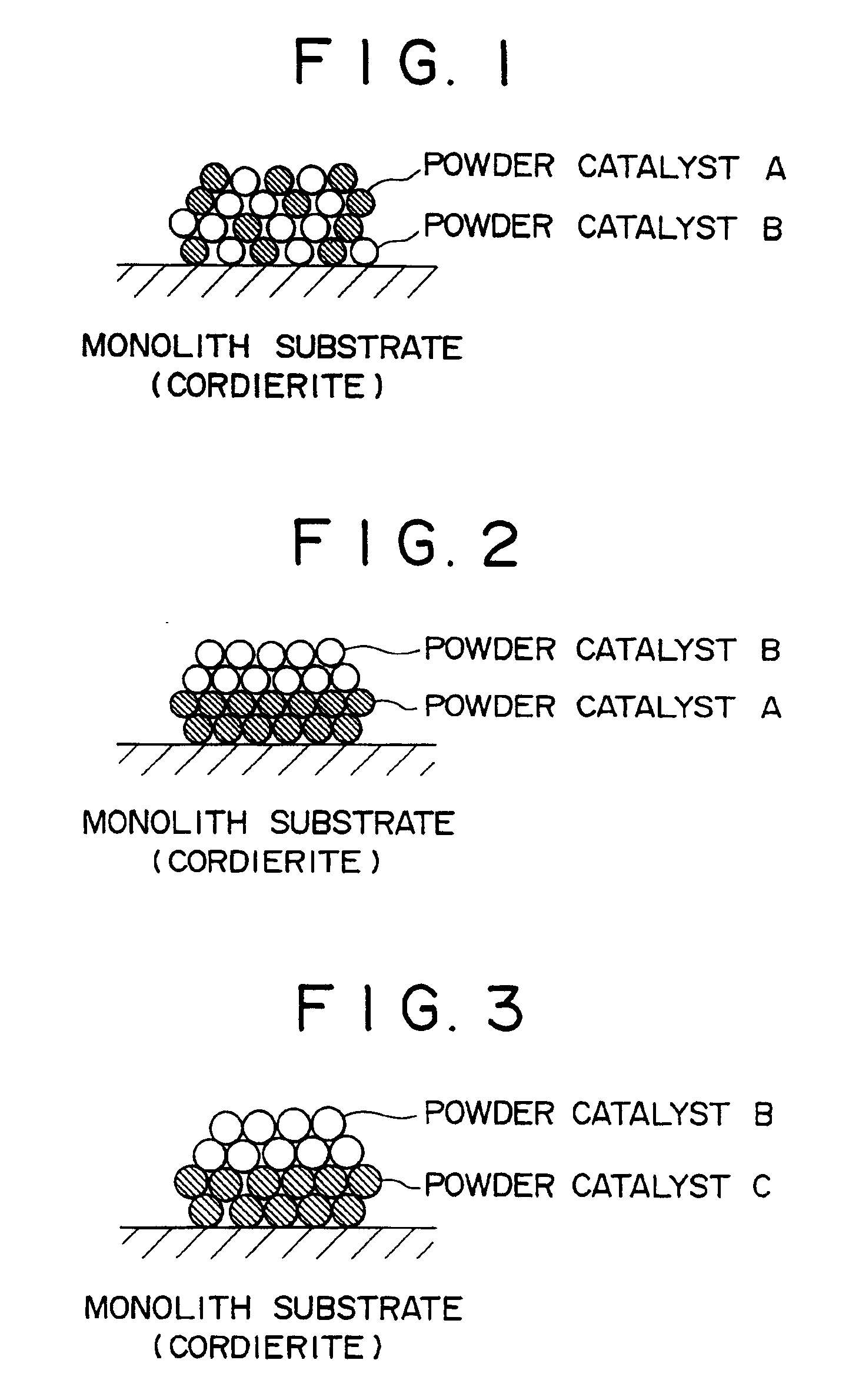
Ammonia decomposition catalysts

a technology of ammonia decomposition and catalyst, which is applied in the direction of catalyst activation/preparation, physical/chemical process catalyst, separation process, etc., can solve the problems of large ammonia release into the atmosphere, large amount of ammonia emitted from various chemical plants, etc., and achieve high efficiency

Inactive Publication Date: 2006-03-28
MITSUBISHI HEAVY IND LTD
View PDF6 Cites 6 Cited by
  • Summary
  • Abstract
  • Description
  • Claims
  • Application Information

AI Technical Summary

Benefits of technology

[0008]An object of the present invention is to provide an ammonia decomposition catalyst capable of decomposing and removing ammonia with a high efficiency without producing by-products nitrogen oxides which may cause air pollution, whereby solving the problems associated with the conventional method described above.

Problems solved by technology

As a result, a large amount of ammonia is emitted from various chemical plants, industrial waste disposal facilities for such things as refrigerators, and combustion exhaust gas treatment facilities.
In reality, however, the formation of ammonia by degradation of organisms, emission of ammonia from coolants in disposed machines, and emission of unreacted ammonia in the reduction process of nitrogen oxides in flue gases result in the release of large amounts of ammonia into the atmosphere.
However, when using a conventional catalyst NO, NO2 and N2O are generated as a result of the side reactions shown below and cause the another problem of air pollution.

Method used


Image

  • Ammonia decomposition catalysts
  • Ammonia decomposition catalysts

Examples


experiment 1

[0047]Ammonia decomposition test was conducted using honeycomb catalysts 1 to 29. Honeycomb catalysts 1 to 29 consisting of 144 cells in the dimension of 15×15×60 mm were placed in a reaction tube, to which ammonia gas having the composition shown below was supplied at SV=16300h−1 and at the flow rate of 5.54Nm3 / m2 to examine ammonia decomposition performance at the reaction temperatures of 300° and 400° C. Gas composition:[0048]NH3: 20 ppm[0049]SO2: 20 ppm[0050]CO2: 7%[0051]H2O: 6%[0052]O2: 14.7%[0053]N2: to 100%

[0054]Performance was evaluated by determining the ammonia decomposition ratio at the initial state of the reaction, NOx (NO, NO2, N2O) production ratio, and SO2 oxidation ratio.

[0055]The ammonia decomposition ratio and NOx production ratio were calculated according to the formulae shown below.[0056]Ammonia decomposition ratio (%)[0057] =[(Inlet NH3−Outlet NH3) / (Inlet NH3)]×100[0058]NOx production ratio (%)=[0059] [(Outlet (N2O×2+NO+NO2)) / (Inlet NH3)]×100[0060]SO2 oxidation...

experiment 2

[0064]Using honeycomb catalysts 1 to 29, the gas was supplied for a long period in the condition similar as in Experiment 1 to conduct durability evaluation test. The results obtained indicated that after the gas supply for 1000 hours in the condition described above the ammonia decomposition ratio, NOx production ratio and SO2 oxidation ratio equivalent to those shown in Table 4 were maintained, ensuring that the catalysts had excellent durability.

[0065]Preparation of catalysts belonging to catalyst A of the second aspect

Preparation of powder catalyst 1

[0066]100 g of crystalline silicate 16f type H described above was immersed in the aqueous solution of iridium chloride (1 g of IrCl in 100 cc of water), kneaded thoroughly, and then evaporated to dryness at 200° C. After purging with nitrogen for 12 hours at 500° C., powder catalyst 1 which is classified to catalyst A was obtained.

Preparation of powder catalysts 2 to 15

[0067]Crystalline silicate 2 to 15 of type H listed above were i...

experimental example 3

[0082]Honeycomb catalysts 30 to 95 were subjected to the ammonia decomposition test similarly as in Example 1. The results are shown in Tables 7 and 8.


PUM

PropertyMeasurementUnit
temperatureaaaaaaaaaa
molar ratioaaaaaaaaaa

Abstract

An ammonia decomposition catalyst wherein a first catalyst having a crystalline silicate which is represented by the formula in terms of molar ratio of oxides as dehydrated:
(1±0.8)R2O.[aM2O3.bM′O.cAl2O3].ySiO2,
wherein R denotes an alkaline metal ion and/or hydrogen ion, M denotes a VIII Group element, rare earth element, titanium, vanadium, chromium, niobium, antimony or gallium, M′ denotes magnesium, calcium, strontium or barium, a≧0, 20>b≧0, a+c=1, 3000>y>11 or a specific porous material as a carrier and iridium or a noble metal as an active metal is present together with or covered with a second catalyst having at least one element selected from the group consisting of titanium, vanadium, tungsten and molybdenum, if necessary, as well as a method of using the same.

Description

BACKGROUND OF THE INVENTION[0001]1. Field of the Invention[0002]The present invention relates to a catalyst for decomposing ammonia contained in waste gases to nitrogen and a method of using the same for ammonia decomposition.[0003]2. Description of the Related Art[0004]Ammonia is widely used as a starting material for fertilizers and nitric acid as well as a reducing agent for removal of nitrogen oxides (NOx) in coolants and exhaust gases. As a result, a large amount of ammonia is emitted from various chemical plants, industrial waste disposal facilities for such things as refrigerators, and combustion exhaust gas treatment facilities.[0005]Ammonia is a gas having a characteristic irritating odor, and should be emitted into the atmosphere as little as possible. In reality, however, the formation of ammonia by degradation of organisms, emission of ammonia from coolants in disposed machines, and emission of unreacted ammonia in the reduction process of nitrogen oxides in flue gases r...

Claims


Application Information

Patent Timeline
Patent Type & Authority Patents(United States)
IPC IPC(8): C01B3/04B01D53/86B01J29/04B01J29/08B01J29/18B01J29/70B01J37/02
CPCB01D53/8634B01J29/04B01J29/082B01J29/084B01J29/18B01J29/7003B01J37/0246Y02E60/36
Inventor NOJIMA, SHIGERUTOKUYAMA, RIEIIDA, KOUZO
Owner MITSUBISHI HEAVY IND LTD
Why Eureka
Try Eureka