

car brake pads
A technology for brake pads and automobiles, applied in the field of brake pads, can solve the problems of easy entry into the lungs, poor thermal conductivity, braking failure, etc., and achieve the effects of reducing noise pollution, long service life, and slowing down energy transmission.
- Summary
- Abstract
- Description
- Claims
- Application Information
AI Technical Summary
Problems solved by technology
Method used
Image

Examples
Embodiment 1
[0023] An automobile brake pad, which comprises a steel back and a friction material bonded on the steel back, wherein the friction material comprises the following components by weight: 5 parts of butyl butylbenzene, peroxide Hydrogen cumene 1 part, epoxy resin 2 parts, boron phenolic resin 6 parts, polypropylene 6 parts, nylon powder 6 parts, boron nitride 6 parts, silane coupling agent A-1510.01 parts, cumene peroxide 2 parts 1 part of sulfur powder, 1 part of benzoic acid, 1 part of stearic acid, 1 part of boric acid, 55 parts of graphite, 5 parts of ceramic fiber, 1 part of potassium titanate, 1.95 parts of reduced iron powder, 1.5 parts of barium sulfate, aluminum alum 1 part of soil, 1 part of feldspar powder, 1 part of zinc oxide, 0.02 part of accelerator TT, 0.02 part of N-phenyl-2-naphthylamine, 1 part of fluorspar powder, 1 part of silicon carbide, and 1 part of coumarone.
[0024] The preparation method of the automobile brake pad is obtained according to a convent...
Embodiment 2
[0032] An automobile brake pad, which comprises a steel back and a friction material bonded on the steel back, wherein the friction material comprises the following components by weight: 5 parts of butyl butylbenzene, peroxide Hydrogen cumene 1 part, epoxy resin 2 parts, boron phenolic resin 6 parts, polypropylene 6 parts, nylon powder 6 parts, boron nitride 6 parts, silane coupling agent A-1510.01 parts, cumene peroxide 2 parts 1 part of sulfur powder, 1 part of benzoic acid, 1 part of stearic acid, 1 part of boric acid, 60 parts of graphite, 5 parts of ceramic fiber, 0.5 part of potassium titanate, 1.95 parts of reduced iron powder, 1.5 parts of barium sulfate, aluminum alum 1 part of soil, 1 part of feldspar powder, 1 part of zinc oxide, 0.02 part of accelerator H, 0.02 part of N-phenyl-2-naphthylamine, 1 part of fluorspar powder, 1 part of silicon carbide, and 1 part of coumarone.
[0033] The preparation method of this automobile brake pad is with embodiment 1.
Embodiment 3
[0035] An automobile brake pad, which comprises a steel back and a friction material bonded on the steel back, wherein the friction material comprises the following components by weight: 5 parts of butyl butylbenzene, peroxide Hydrogen cumene 1 part, epoxy resin 2 parts, boron phenolic resin 6 parts, polypropylene 6 parts, nylon powder 6 parts, boron nitride 6 parts, silane coupling agent A-1510.01 parts, cumene peroxide 2 parts 1 part of sulfur powder, 1 part of benzoic acid, 1 part of stearic acid, 1 part of boric acid, 50 parts of graphite, 8 parts of ceramic fiber, 1 part of potassium titanate, 1.95 parts of reduced iron powder, 1.5 parts of barium sulfate, aluminum alum 1 part of soil, 1 part of feldspar powder, 1 part of zinc oxide, 0.02 part of accelerator M, 0.02 part of N-phenyl-2-naphthylamine, 1 part of fluorspar powder, 1 part of silicon carbide, and 1 part of coumarone.
[0036] The preparation method of this automobile brake pad is with embodiment 1.
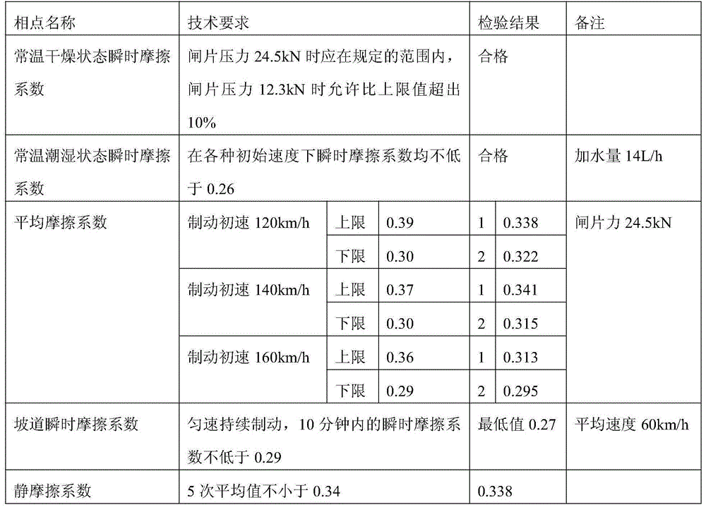
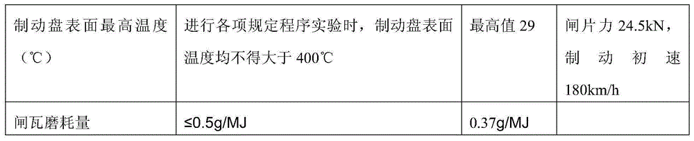
[0037] To...
PUM
 Abstract
Description
Claims
Application Information