Method for emission reduction of CO2 and yield increase of methyl alcohol and acetic acid by means of CO2 emission reduction integrated unit adopted in coal-to-methanol and coal-to-acetic acid processes

A coal-to-methanol and combined device technology, applied in chemical instruments and methods, carbon monoxide reaction to prepare carboxylic acid, and combustible gas, can solve the problems of polluting the environment, aggravating the greenhouse effect, and large combustion volume

Inactive Publication Date: 2016-11-09
HENAN LONGYU COAL CHEM
View PDF7 Cites 6 Cited by
  • Summary
  • Abstract
  • Description
  • Claims
  • Application Information

AI Technical Summary

Problems solved by technology

During this process, the direct venting of carbon dioxide in the acid removal device will carry a small amount of hydrogen sulfide gas and methanol with obvious peculiar smell and toxicity, which is harmful to human health, working environment and living environment; moreover, carbon dioxide gas as a Gases that are widely used in industry and food industry and have high economic value, direct emissions not only cause serious waste of resources, but also aggravate the global greenhouse effect
[0004] In the pressurized gasification of pulverized coal, nitrogen is used as the inert protective gas and conveying gas of the pulverized coal conveying system, the ultra-high pressure blowback gas of the gasifier, the sealing gas of the quenching gas compressor and the purge gas of the impeller. The use of nitrogen in the process has major disadvantages: (1) Consuming a large amount of nitrogen requires air separation to increase its own load to provide it, which will cause an increase in the consumption of the air separation unit and waste of nitrogen resources; (2) a large amount of nitrogen enters the gasifier , and synthesis gas (mainly CO, H 2 ) reacts to generate a large amount of ammonia nitrogen, which increases the difficulty of the preliminary water treatment system of the coal gasification unit and the downstream sewage system; (3) a large amount of nitrogen entering the synthesis gas will cause the methanol synthesis unit downstream of the coal gasification unit to vent gas The amount of combustion is large, resulting in the waste of a large amount of effective gas and the venting of a large amount of carbon dioxide gas generated during the combustion process; (4) the large amount of carbon dioxide gas produced by low-temperature methanol washing is vented, which not only causes a waste of resources, but also pollutes the environment and aggravates the The greenhouse effect is not conducive to enterprises to reduce emissions and increase efficiency, reduce losses and increase profits under the new economic normal and increasingly urgent environmental protection pressure

Method used


Image

  • Method for emission reduction of CO2 and yield increase of methyl alcohol and acetic acid by means of CO2 emission reduction integrated unit adopted in coal-to-methanol and coal-to-acetic acid processes

Examples


Embodiment 1

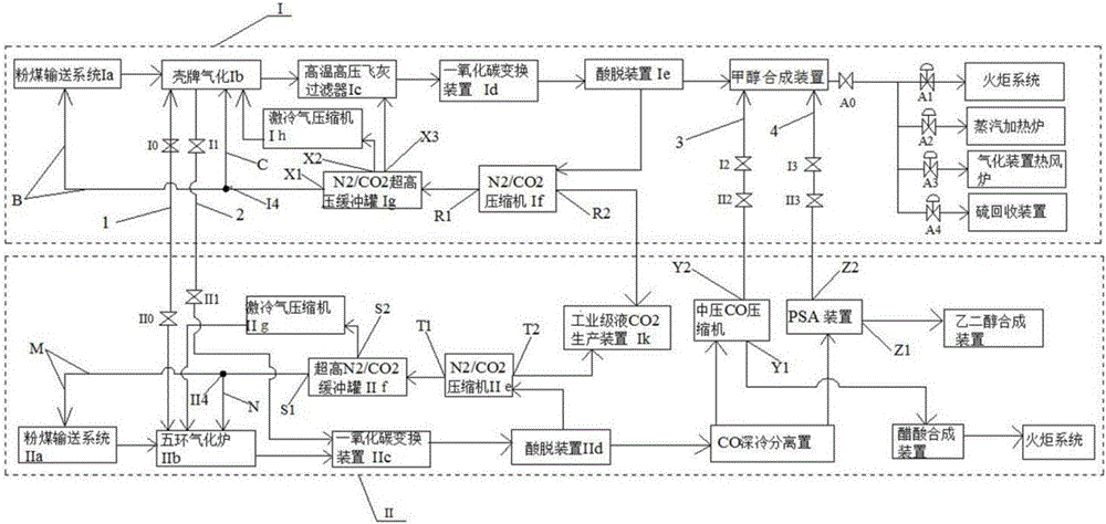
[0035] CO emission reduction in coal-to-methanol and coal-to-acetic acid processes 2 combined devices, such as figure 1 Shown: The device includes coal-to-methanol plant I, coal-to-acetic acid plant II, CO 2 Connect the pipe network 1, and the gas delivery pipeline connecting the coal-to-methanol unit and the coal-to-acetic acid unit, the gas delivery pipeline includes crude gas delivery pipeline 2, hydrogen H 2 Gas delivery pipeline 4 and carbon monoxide CO gas delivery pipeline 3.

[0036] Wherein, the coal-to-methanol unit I includes a pulverized coal delivery system Ia, a Shell gasifier Ib, a high-temperature and high-pressure fly ash filter Ic, a CO conversion unit Id, an acid removal unit Ie, a methanol synthesis unit, a flare system, and steam heating Furnace, gasification unit hot blast stove, sulfur recovery unit, N 2 / CO 2 Compressor If, super high pressure N 2 / CO 2 Buffer tank Ig, chilled gas compressor Ih and industrial grade liquid CO 2 Production device I...

Embodiment 2

[0042] Using coal to methanol and coal to acetic acid to reduce CO emissions 2 Combined plant emission reduction CO 2 And the method for increasing production of methanol and acetic acid comprises the following steps:

[0043] (1) Start the coal-to-methanol unit Ⅰ. After the start-up, the pulverized coal enters the pulverized coal delivery system Ⅰa under the action of the carrier gas nitrogen, and utilizes the pressure difference between the pulverized coal delivery system Ⅰa and the Shell gasifier Ⅰb to 11.20kg The amount of coal input per second is to put coal powder into the Shell gasifier, and at the same time, feed oxygen into the Shell gasifier at a rate of 10.67kg / s with a mass flow rate until the oxygen load is 58%. The mass ratio of the reaction gasifier is 1-1.05, and then the reaction is carried out in the gasifier at a pressure of 0.5-0.8MPa and a temperature of 1400-1600°C; when the pressure in the reaction gasifier is 3.0-4.0MPa, the gasifier When the oxygen l...


PUM

PropertyMeasurementUnit
clearance rateaaaaaaaaaa

Abstract

The invention discloses a method for emission reduction of CO2 and yield increase of methyl alcohol and acetic acid by means of a CO2 emission reduction integrated unit adopted in coal-to-methanol and coal-to-acetic acid processes. The integrated unit comprises a coal-to-methanol device and a coal-to-acetic acid device, a CO2 connection pipe network connected with the coal-to-methanol device and the coal-to-acetic acid device, and a gas delivery pipeline connected with the coal-to-methanol device and the coal-to-acetic acid device. The method comprises the steps of starting the coal-to-methanol device firstly; opening the CO2 connection pipe network and starting the coal-to-acetic acid device after the coal-to-methanol device runs for a certain period of time, wherein qualified gas generated during operation of the coal-to-acetic acid device is used for preparing acetic acid, and unqualified gas enters a methanol synthesis device through the gas delivery pipeline to be recycled. The byproduct CO2 generated from methanol preparation is recycled to the coal-to-methanol device and the coal-to-acetic acid device, CO2 emission is reduced greatly, useful gas generated in the coal-to-acetic acid process is used for preparing methanol and acetic acid, the yield of methanol and acetic acid is increased, and economic and social benefits are remarkable.

Description

technical field [0001] The invention belongs to the technical field of coal gasification production, and relates to a coal-to-methanol and coal-to-acetic acid combined device, in particular to a CO reduction process using coal to methanol and coal to acetic acid. 2 Combined plant emission reduction CO 2 And increase the production of methanol and acetic acid method. technical background [0002] The production and operation of large-scale coal chemical plants are all accompanied by the venting of a large amount of carbon dioxide gas. According to incomplete statistics, coal-to-methanol and acetic acid plants with an annual production capacity of 500,000 tons have an average annual carbon dioxide emission of more than 2.3 million tons . Under the increasingly severe situation of environmental protection work in my country and even the world, in the situation of continuous slump in the coal chemical industry market, especially in the case of the continuous increase in the sc...

Claims


Application Information

Patent Timeline
Patent Type & Authority Applications(China)
IPC IPC(8): C07C29/152C07C31/04C07C51/10C07C53/08C10J3/48C10J3/84C10J3/72
CPCC10J3/48C07C29/152C07C51/10C10J3/72C10J3/84C10J2300/1603C10J2300/1612C07C31/04C07C53/08
Inventor 崔发科牛玉奇谢肥东沈小炎杜霞陈磊黄孺国孟斌李星崔小明
Owner HENAN LONGYU COAL CHEM
Why Eureka
Try Eureka