Waste incineration fly ash recycling method and system

A waste incineration fly ash and treatment system technology, applied in waste heat treatment, furnace control devices, lighting and heating equipment, etc., can solve problems such as energy consumption, high energy consumption of plasma treatment technology, secondary hazardous waste, etc., and achieve flue gas The effect of small emissions, increased proportion, and reduced equipment investment

Active Publication Date: 2021-02-26
XIAN AEROSPACE SOURCE POWER ENG CO LTD
View PDF6 Cites 3 Cited by
  • Summary
  • Abstract
  • Description
  • Claims
  • Application Information

AI Technical Summary

Problems solved by technology

The conventional method is to wash the fly ash with water. The disadvantage of this method is that it will produce waste water rich in heavy metals and secondary hazardous waste;

Method used


Image

  • Waste incineration fly ash recycling method and system
  • Waste incineration fly ash recycling method and system
  • Waste incineration fly ash recycling method and system

Examples


Embodiment 1

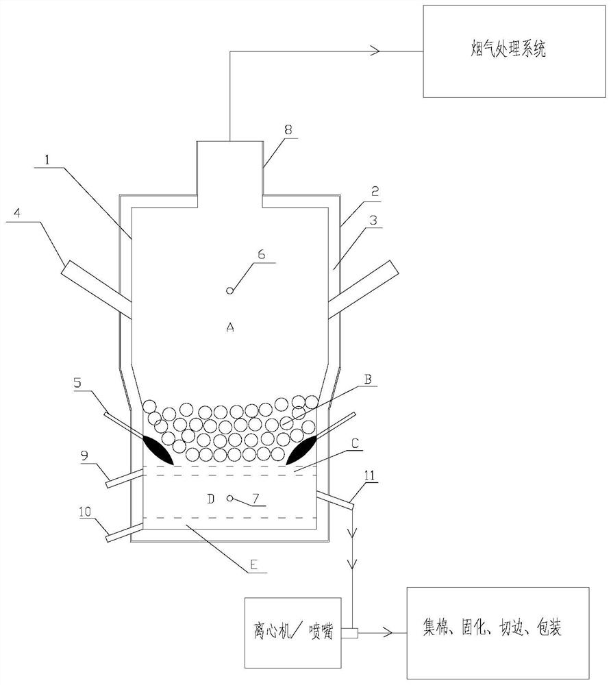
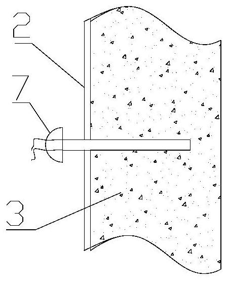
[0036] The waste incineration fly ash recycling system of this embodiment, such as figure 1 As shown, it is specifically a pure oxygen combustion melting furnace 1. The pure oxygen combustion melting furnace 1 is composed of a furnace wall 2 and a refractory material 3. The furnace can be divided into a gas phase area A, a fly ash particle solid phase area B, and a chloride salt melting area C. , slag zone D, alloy melting zone E;

[0037] In the gas phase area A, two feed ports 4 are evenly distributed along the furnace wall to ensure the uniformity of the feed. The angle between the feed port and the furnace wall is 40°; the top of the furnace body is provided with a smoke exhaust port;

[0038] Two pure oxygen burners 5 are evenly distributed in the solid phase area B of fly ash particles to ensure the uniformity of temperature in the solid phase and liquid phase areas of the fly ash fusion, and the angle between the pure oxygen burner and the furnace wall is 40°;

[0039]...

Embodiment 2

[0044] Adopt the stove of embodiment 1 to be example to fly ash, the material composition analysis of this fly ash is as shown in table 1:

[0045] Table 1

[0046] components Mass fraction % SiO 2

[0047] Taking 1t of fly ash in Table 1 as an example, add 300kg of limestone and 80kg of starch as a binder to granulate before putting into the furnace. The granulated particle size is 30-50mm.

Embodiment 3

[0049] Taking 1t of fly ash in Table 1 as an example, add 320kg of quartz sand (purity 98%) and 100kg of starch as a binder to granulate before putting into the furnace, with a particle size of 30-50mm. The granulation formula can ensure the acidity coefficient Mk=1.2 after the fly ash is melted, which meets the composition requirement of slag wool.

[0050] The granulated material is fed into the pure oxygen combustion melting furnace from the feed port 4. By controlling the height of the solid material, the temperature of the gas phase zone A in the furnace is maintained at 500-700°C. At the same time, by adjusting the pure oxygen burner The amount of natural gas is used to maintain the temperature of the melting zone at 1500-1600°C.

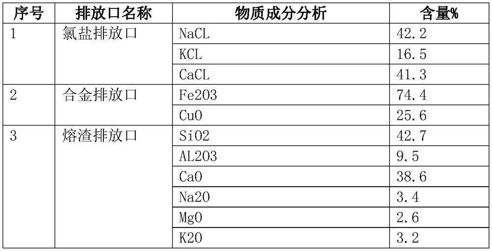
[0051] Table 2 shows the chemical analysis results of the chlorine salt discharge port discharge, the alloy discharge port discharge material, and the slag discharge port discharge material in this embodiment.

[0052] Table 2

[0053]

...


PUM


Abstract

The invention discloses a waste incineration fly ash recycling method and system. The waste incineration fly ash recycling method comprises the following steps that 1, after fly ash particles are fedinto a furnace from a feeding port in an upper area of a furnace body, the fly ash particles are cooled to a middle-lower area in the furnace to be combusted and melted by a pure oxygen combustor, andsmoke generated in the melting process rises to the temperature of 500-700 DEG C in an upper area in the furnace and then is exhausted; 2, a liquid chlorine salt layer, a slag layer and a liquid alloy layer are formed from top to bottom in the process that molten liquid sinks to a bottom area in the furnace; and 3, the liquid chlorine salt layer, the slag layer and the liquid alloy layer are recycled in a layered manner. The waste incineration fly ash recycling system mainly comprises a melting furnace, and a gas phase area, a solid phase area, a chlorine salt melting area, a slag area and analloy melting area are sequentially arranged in the melting furnace from top to bottom. According to the waste incineration fly ash recycling method and system, the heat utilization rate is high, theflue gas emission is small, and the equipment investment of a subsequent flue gas treatment system can be reduced; Moreover, after fly ash is treated by the method, chlorine salt, alloy and slag layers are formed after the fly ash is molten, and all the layers can be recycled.

Description

technical field [0001] The invention belongs to the technical field of resource utilization of fly ash, and relates to a system and method for resource recovery of waste incineration fly ash. Background technique [0002] During the operation of waste incineration boilers, a large amount of fly ash will be produced, accounting for about 3%-5% of the incineration. Because fly ash contains a large amount of heavy metals and dioxins, it causes serious pollution to the environment. The existing fly ash treatment method is "solidification + landfill". However, landfilling takes up a lot of land resources, and the leachate may also pollute the environment. [0003] At present, after the fly ash is melted by plasma technology, the dioxins in the fly ash can be effectively decomposed, and the heavy metals are solidified in the glass body, and then used as building materials for recycling. However, because fly ash is often rich in chloride salts, it mainly exists in the form of so...

Claims


Application Information

Patent Timeline
IPC IPC(8): F27B17/00F27D3/14F27D17/00F27D19/00
CPCF27B17/00F27D3/14F27D17/004F27D17/008F27D19/00F27D2019/0003Y02P10/20
Inventor 仲伟聪吉彦鹏张春飞汪刚刘丹朱宝飞周楠张绍峰喻澎清
Owner XIAN AEROSPACE SOURCE POWER ENG CO LTD
Why Eureka
Try Eureka