Effluent gas stream treatment system having utility for oxidation treatment of semiconductor manufacturing effluent gases

a technology for oxidation treatment and effluent gas, which is applied in the field of system for the treatment of industrial effluent fluids, can solve the problems of generating particulates, poor scrubber section scrubbing of acid gas, and clear less convenient end user implementation of such a consolidated equipment approach than for the original equipment manufacturer. , to achieve the effect of reducing the susceptibility to clogging and reducing the amount of water required

Inactive Publication Date: 2002-02-14
APPLIED MATERIALS INC
View PDF52 Cites 23 Cited by
  • Summary
  • Abstract
  • Description
  • Claims
  • Application Information

AI Technical Summary

Benefits of technology

[0017] It is a further object of the invention to provide an improved system for the treatment of industrial effluent gases, which reduces the susceptibility to clogging and solids accumulations in the system.
[0056] 10. The utilization of a transpiration tube reactor design for the oxidizer unit to eliminate wall accumulations of reactant / product solids in the oxidation step.

Problems solved by technology

Nonetheless, the execution of such a consolidated equipment approach is clearly less convenient for the end user than for the original equipment manufacturer, since the original equipment manufacturer can provide an integration of the various operational treatment units in a single small-sized treatment system in the first instance.
Additionally, while these original equipment manufacturer-integrated effluent gas stream treatment systems clearly can, in certain applications, have advantages over single unit operational systems, typically, these integrated systems, which may for example carry out unit operations of oxidation, quenching, and scrubbing, suffer from various deficiencies, including: particulates clogging in the respective sections as well as the inlet region of the oxidizer section, generation of particulates in the oxidation section, poor scrubbing of acid gases in the scrubber section, high consumption of water for acid gas and particulate scrubbing, and condensation of saturated off-gases from the scrubber section resulting in collection and concentration of aqueous mixtures with acids.
These inlet clogging problems may require the incorporation of plunger mechanisms or other solids removal means to keep the inlet free of solids accumulations, however these mechanical fixes add considerable expense and labor to the system.
In other instances, the inlet clogging problems may be systemic and require periodic preventative maintenance to keep the inlet free of solids accumulations.
Such maintenance, however, requires shut-down of the system and loss of productivity in the manufacturing facility.
The existing integrated point of use gas effluent treatment systems may also experience problems in plant facilities which have difficulty in treating the wastewater from their wet scrubbing processes.
A number of plants may have difficulties processing the fluorine (F) species in the wastewater generated from these point of use systems, or more generally, in processing wastewater deriving from the gas effluent treatment system per se.
The water scrubber and quench portions of the integrated system can also have problems with clogging when quality of the feed water available to the process facility is poor, a typical condition in the Southwest United States.
Lack of readily available water, high water costs, and high disposal costs for discharged wastewater are also significant problems in many localities.
While effective in preventing the scrubber and quench plugging, such solution involves a very high cost of ownership associated with the substantial costs of high quality deionized water.
In the scrubbing operation, poor scrubbing of acid gases in scrubber towers can be due to the small flowrates that are processed through these systems.
The diameters of scrubber towers processing such small flowrates are correspondingly small, which when combined with the use of conventional large diameter packing can result in a packing element diameter to column diameter which is excessively high and results in large wall effects in the scrubber tower.
Such scrubber towers as a result require large water flows, which in turn can cause channeling, flooding and slugging, with pockets of process gas passing untreated through the scrubber system.
Due to the poor scrubbing of these systems, corrosion in the ducting downstream of these systems is commonly observed, which is due to condensation of the untreated off-gases from the scrubber.
When halide gases are being treated in the effluent stream, the off-gases from the scrubber tower will as a result of the poor scrubbing performance of the scrubber contain unscrubbed halogen content.
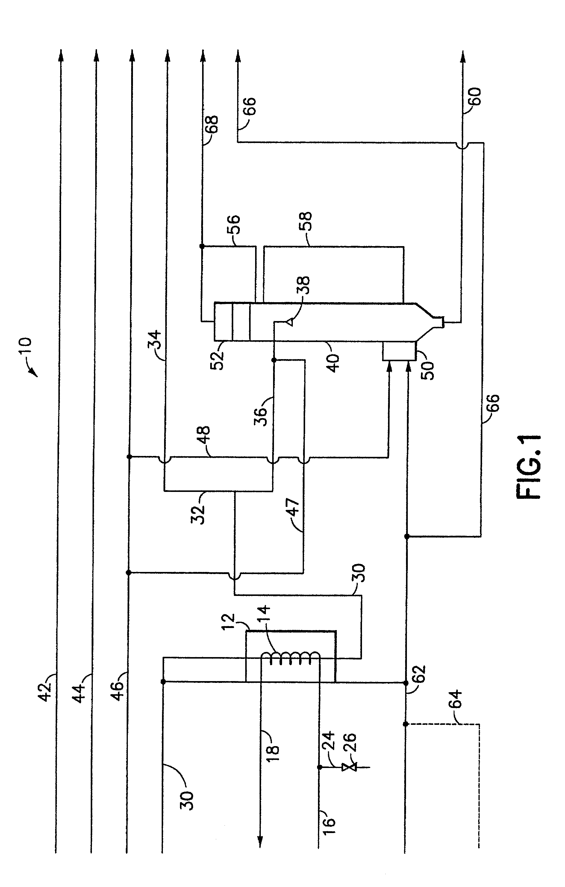
1. The provision of a totally integrated gas effluent stream treatment system in a unitary cabinet configuration including a non-clogging inlet, pre-scrubber, oxidizer, wet / dry interface, quench, post-scrubber and motive means.
2. The use of a pre-treatment subsystem for hydrogen fluoride absorption. Such pre-treatment subsystem is in essence utilized as a particulate pre-removal system by removing particulate precursors rather than trying to remove fine particulates formed during the oxidation process.
3. The provision of a wet / dry interface of a slit / hole injection type or of a porous type interface, which can substantially reduce water usage and render system leveling unnecessary.
4. The provision of a shell and tube heat exchanger type oxidizer using radiative flux as a working "fluid" on the shell side.
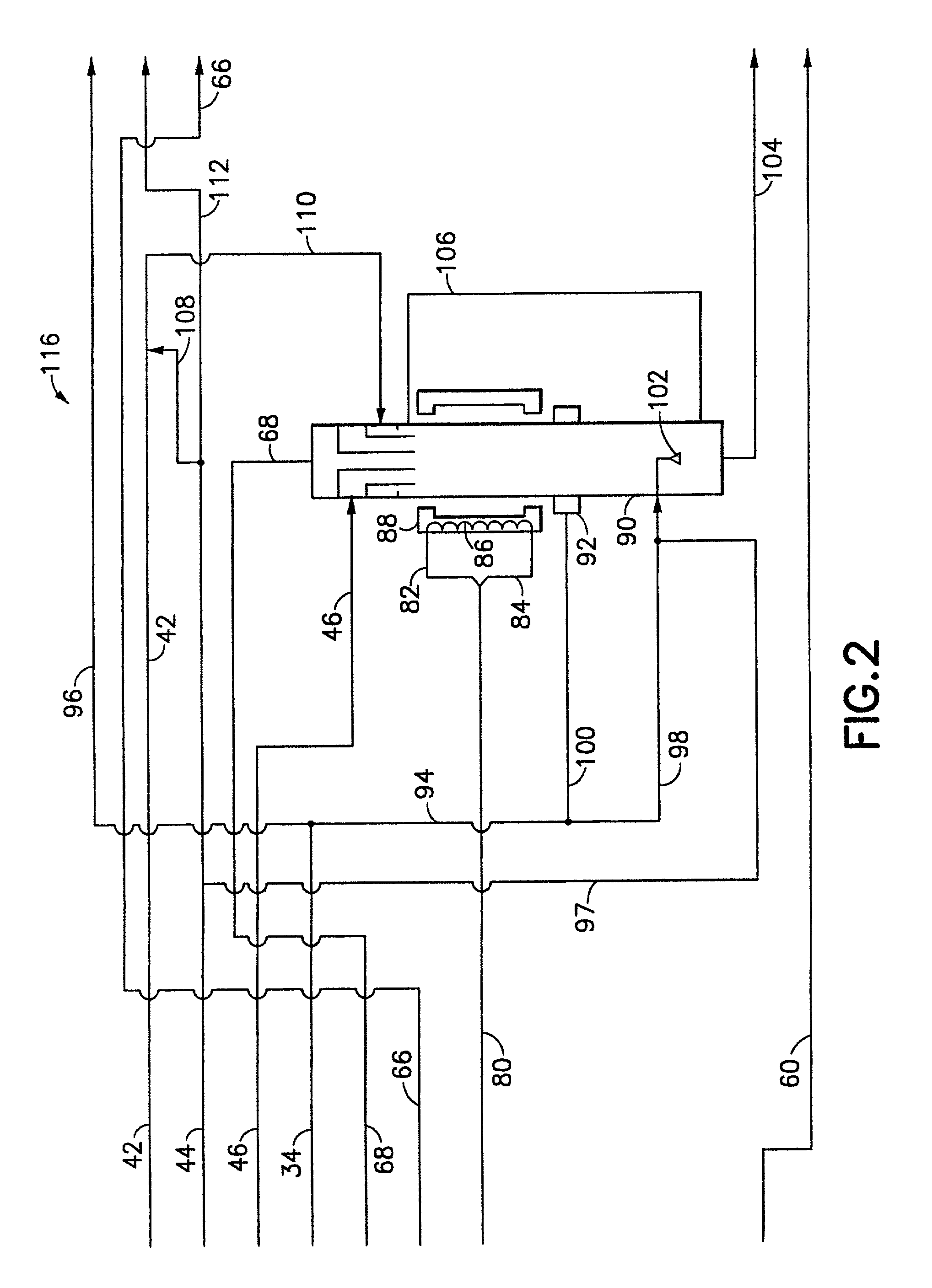
5. The provision of sub-cooling in the water scrubber (together with other features hereinafter more fully described) yielding a condensationless or minimum-condensation design and enhanced thermophoretic acid gas and particulate scrubbing; additionally, an ejector for fluid discharge may be employed to render the effluent gas treatment system "invisible" to the exhaust line of the processing system, or such discharge means may be employed to increase the draw on the upstream process unit (e.g., semiconductor manufacturing tool) if necessary.
6. The use of a demister mesh as a packing element in the scrubber column. Such demister mesh can substantially reduce wall effects in scrubber columns of small diameter. Mass transfer and heat transfer in the scrubber column as a result are comparable to or better than scrubber column performance with standard commercially available random packings, and demister mesh-containing scrubber columns achieve relatively low pressure drop. The void fraction at the top of the scrubber column can also be flexibly designed to constitute the scrubber column as a good particle collector; random packings are not as flexible and do not readily permit the flexibility achievable with demister mesh-containing scrubber columns.
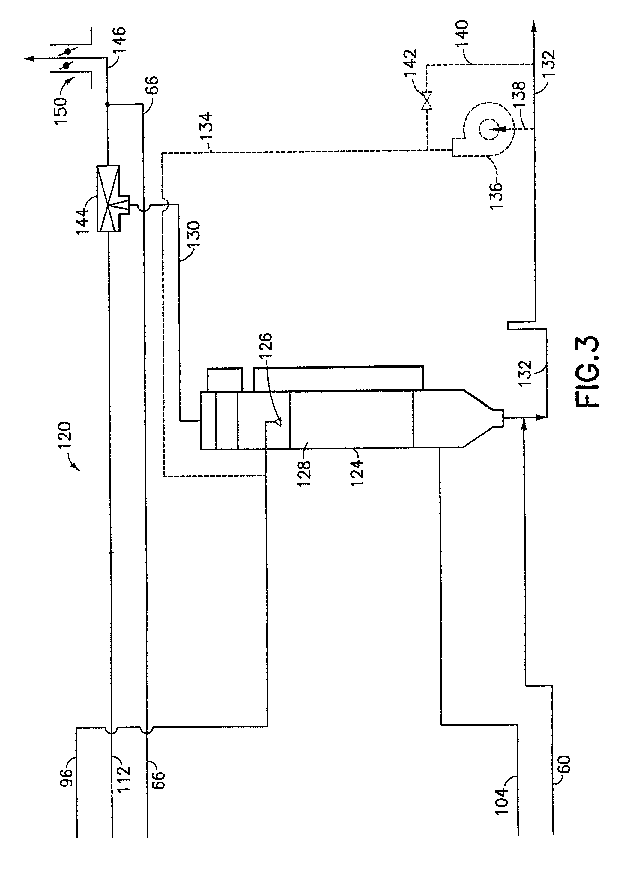
7. The use of heat transfer enhancement inserts in the oxidizer to tailor the effluent gas stream treatment system to applications requiring varying thermal fluxes in the overall operation of the system.
8. The recycle of a saturated H.sub.2O / exhaust stream from the quench of an oxidizer unit in the effluent gas treatment system to the inlet of the oxidizer unit provides a low cost hydrogen source for oxidation of perfluorocarbons (PFCs).
9. The addition of chemicals into the pre-scrubber may be employed to alter the characteristics of the materials to be scrubbed. An illustrative example is the addition of NH.sub.3 to tungsten hexafluoride effluent to form ammonium tungstate, thereby yielding a material with elevated solubility for scrubbing removal thereof.

Method used


Image

  • Effluent gas stream treatment system having utility for oxidation treatment of semiconductor manufacturing effluent gases
  • Effluent gas stream treatment system having utility for oxidation treatment of semiconductor manufacturing effluent gases
  • Effluent gas stream treatment system having utility for oxidation treatment of semiconductor manufacturing effluent gases

Examples


Embodiment Construction

[0076] The objective of the present invention is to provide an improved gas effluent treatment system, which may be utilized to treat a wide variety of effluent gas streams, deriving from correspondingly diverse industrial processes.

[0077] In one aspect, the present invention contemplates a system for oxidation treatment of an effluent gas stream deriving from an upstream process unit generating such effluent, in which oxidization and scrubbing processes are carried out, to abate hazardous or otherwise undesired species in the effluent gas stream.

[0078] In a particular aspect, such effluent gas stream treatment system may comprise oxidation and scrubbing unit operations, in which the system is constructed and arranged to minimize the adverse effect of solid particulates in the gas stream, such as may derive in the first instance from the upstream process, or which may be generated in-situ in the effluent treatment system, e.g., as a result of the oxidation treatment of the effluent ...


PUM

PropertyMeasurementUnit
pore sizeaaaaaaaaaa
pore diametersaaaaaaaaaa
temperaturesaaaaaaaaaa

Abstract

An effluent gas stream treatment system for treatment of gaseous effluents such as waste gases from semiconductor manufacturing operations. The effluent gas stream treatment system comprises a pre-oxidation treatment unit, which may for example comprise a scrubber, an oxidation unit such an electrothermal oxidizer, and a post-oxidation treatment unit, such as a wet or dry scrubber. The effluent gas stream treatment system of the invention may utilize an integrated oxidizer, quench and wet scrubber assembly, for abatement of hazardous or otherwise undesired components from the effluent gas stream. Gas or liquid shrouding of gas streams in the treatment system may be provided by high efficiency inlet structures.

Description

[0001] 1. Field of the Invention[0002] The present invention relates to a system for the treatment of industrial effluent fluids such as effluent gases produced in semiconductor manufacturing, photovoltaic processing, etc. Such system may variously include an oxidizer, gas scrubbing, particulate solids removal, and other unit operations for effluent gas treatment.[0003] 2. Description of the Related Art[0004] In the treatment of industrial fluid waste streams, a wide variety of unit operations and corresponding discrete treatment apparatus have been integrated for processing of the effluent from an upstream process facility.[0005] For example, various integrated thermal systems are commercially available for treatment of semiconductor manufacturing effluents and photovoltaic processing off-gases. These integrated systems are typically targeted for use with CVD, metal etch, etch and ion implant tools. Commercial integrated systems include the Delatech Controlled Decomposition Oxidize...

Claims


Application Information

Patent Timeline
Patent Type & Authority Applications(United States)
IPC IPC(8): B01D53/14B01D53/68C23C16/44
CPCB01D47/06B01D53/14B01D53/1456B01D53/68B01D2258/0216C23C16/4412Y02C20/30
Inventor HOLST, MARKCARPENTER, KENTLANE, SCOTTARYA, PRAKASH V.
Owner APPLIED MATERIALS INC
Why Eureka
Try Eureka