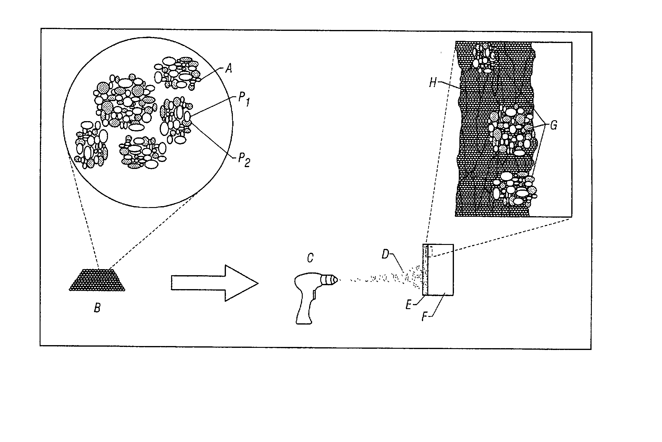
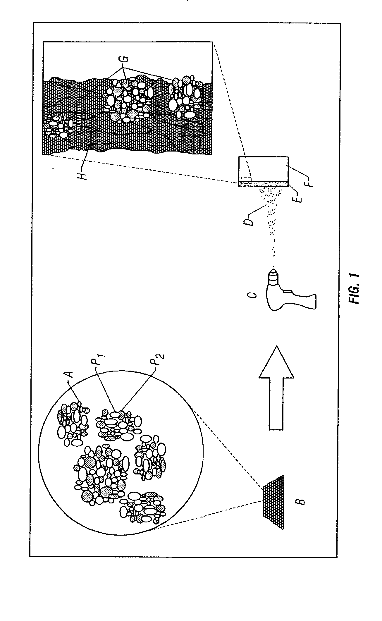
[0010] The present invention is directed to nanostructured titania coatings that can be prepared by
thermal spray coating ultrafine titania agglomerates onto a titanium
substrate surface. The abovementioned and other deficiencies of the prior art are overcome or alleviated by the methods of the present invention, which will enhance the reliability and the life of ball valves by incorporating superior coatings with ultrafine-grain size.
[0023] An important aspect in selecting coating compositions relates to the fact that having a
composite material consisting of two or more fine, well-distributed, and immiscible particles can substantially reduce
grain growth (by
grain boundary pinning) at elevated temperatures. Since thermal spray application of
ceramic coatings relies on heating the particles to molten or semi-molten states, mitigation of
grain growth to maintain an ultrafine-grained coating is of great importance. Also, some wear applications may involve a certain degree of
exposure to elevated temperatures after the coated
ball valve surfaces are placed in industrial use; if the coating does not possess a means of stabilizing the ultrafine
grain structure, the associated
grain growth could change the coating properties.
[0024]
Titanium oxide as the coating base material has an additional benefit for NiHPAL applications, where valves are typically fabricated from
solid titanium. The benefit stems from the similar coefficient of
thermal expansion (CTE) for both the
oxide and metallic states of titanium. This is especially important in thermal spray coatings where residual stresses may form within the coating and at the coating-substrate interface due to differences in thermal expansion and contraction during spraying and cooling, respectively. The similar CTE inhibits premature spalling and minimizes the cross-sections of crack formation within the coating. In addition, the good match in CTE and the good
corrosion resistance of the titanium (by forming a passivated layer of
titanium oxide) excludes the need for adding a metallic
bond coat.
[0030] The ultrafine-grained or nanostructured coating provides enhanced wear-resistance and
toughness, as well as superior
bond strength to the substrate. Corrosion is minimized by a layer of titanium against the coating, which has been passivated by the titania. If desired, an organic or inorganic
sealant can be applied to penetrate the coating and seal any through-micro-cracks and through-
porosity. For example, a viscous
fluoropolymer can be used to impregnate the coating. The application of vacuum can facilitate through penetration of the
fluoropolymer into the coating. These enhanced coating properties, combined with a sound ball valve design, lead to the
processing of more reliable and longer lasting valves.
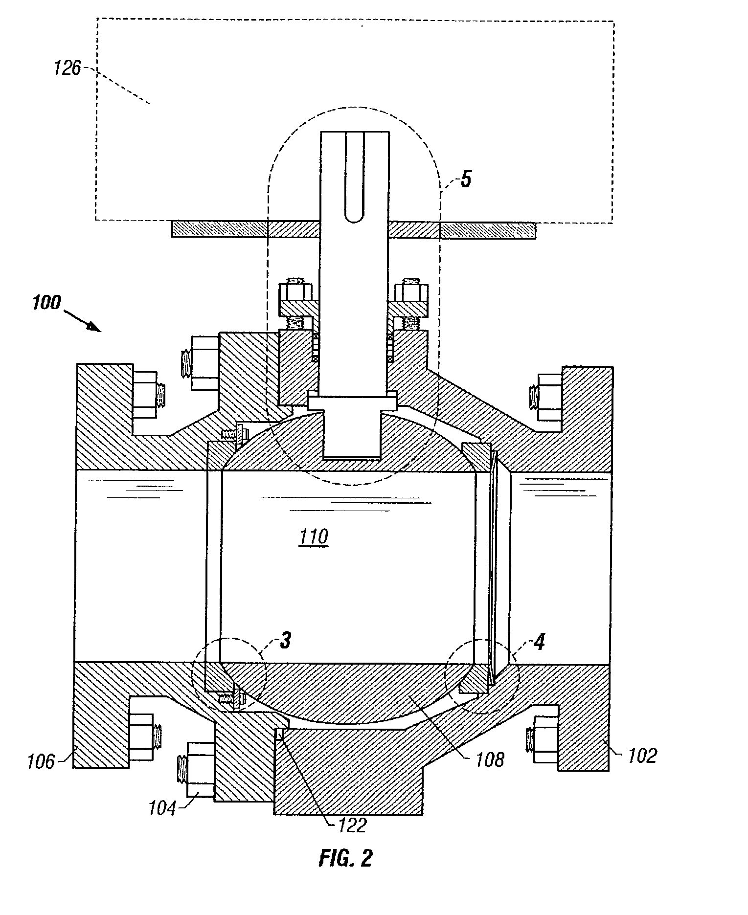
[0032] In the ball valve 100, the titanium parts are generally Grade 12. The stem 124 and spring 114 can be made from Grade 5 titanium, which provides approximately two times the strength of Grade 12 and allows the use of a smaller
diameter stem 124, and hence lower operating torque. Grade 12 or 29 can be used where
crevice corrosion is a concern, e.g.
chloride concentrations greater than 1000 ppm. Grade 29 offers strength and
high resistance to corrosion.
[0033] In operation, the ball valve 100 is a bi-directional seated floating ball valve that can be utilized in pressure leach nickel extraction service, for example. The ball valve 100 is designed for easy maintenance and maximum life under severely erosive and corrosive conditions. The ball valve 100 is typically installed as an
isolation valve in spare, vent, drain,
slurry inlet and
discharge applications on a conventional pressure leach
autoclave (not shown). The ball valve 100 is alternately opened to allow the passage of fluid and closed to prevent the passage of fluid. The fluid passing through the valve or prevented from passing through the valve can be corrosive and contain abrasive particles. The ball 108 and seats 112, 114 are protected from corrosion and
erosion by the titania coatings described above. The use of a retained normal seat prevents
solid particle contamination of critical sealing surfaces to maintain dependable sealing properties.

