Methods and apparatus for conducting multiple measurements on a sample

Active Publication Date: 2003-06-19
MESO SCALE TECH LLC
View PDF29 Cites 380 Cited by
  • Summary
  • Abstract
  • Description
  • Claims
  • Application Information

AI Technical Summary

Benefits of technology

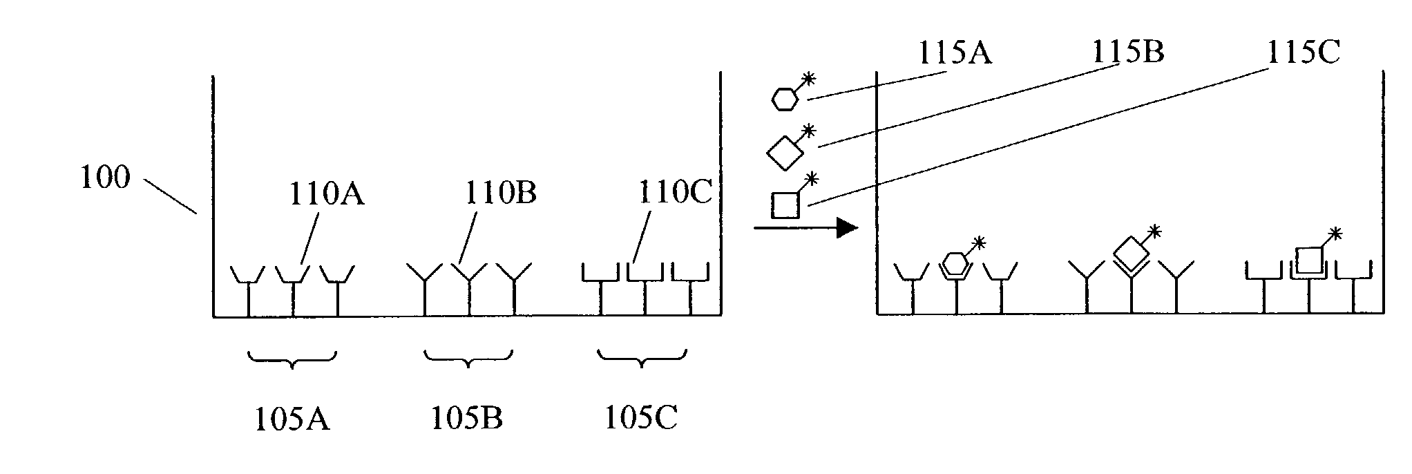
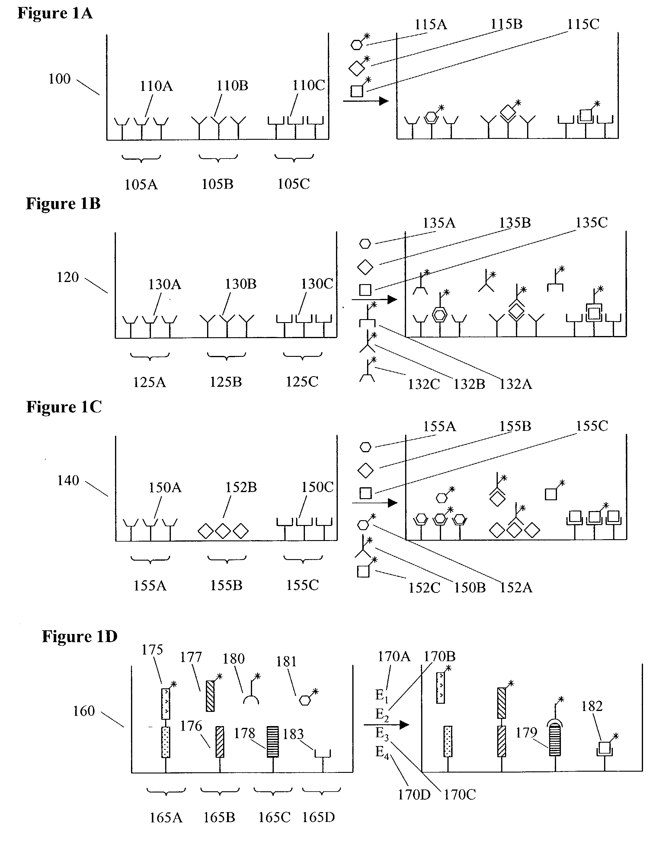
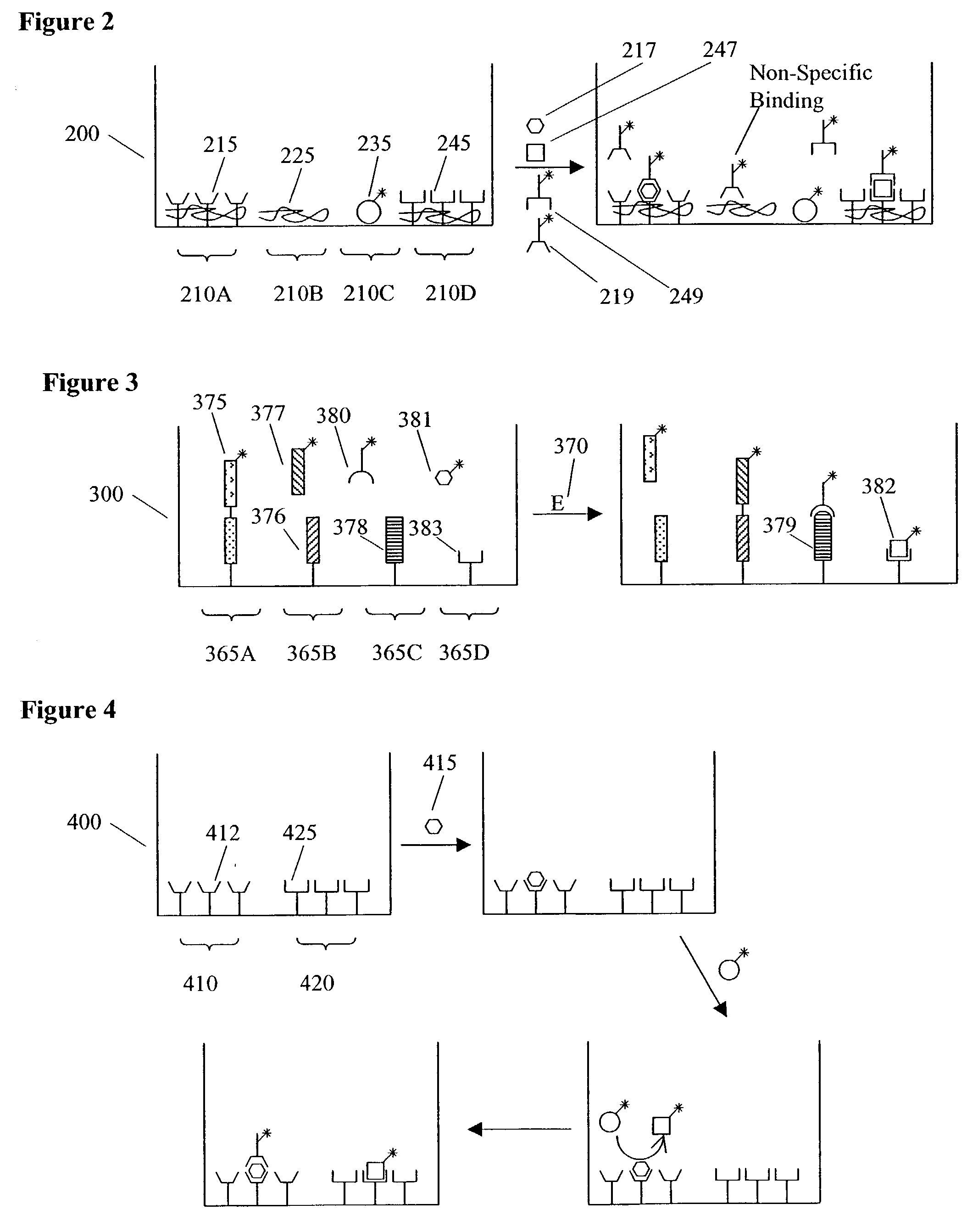
0013] In another preferred assay format the same analyte or activity is measured in multiple domains within a well; such redundancy can allow for greater statistical confidence in an assay result. Such multiple measurements of the same analyte may involve the use of multiple roughly identical assay domains or, alternatively, may involve the use of assay domains that vary in some property (for example, domain size, domain location, surface density of an assay reagent, blocking agent, assay reagent affinity, assay reagent specificity, assay format, sensitivity to interferents, sensitivity to temperature, assay kinetics, sensitivity to optical distortion, etc.) so as to account for, detect, and/or compensate for a source of assay error (e.g., inconsistent or non-homogenous mixing, steric crowding of assay reagents in an assay domain, non-specific binding, matrix effects, interfering species, imprecise temperature control, imprecise timing of assay steps, exceeding of assay dynamic range, variation in fluid volume or meniscus shape, etc.).
0014] In another preferred assay format, the same analyte or activity is measured in multiple domains within a well, the domains being comprised on individually addressable electrodes. In such a system one may measure the kinetics of an assay reaction by sequentially applying electrical energy to individual assay domains at selected times and measuring the change in electrical current, electrical potential, or, preferably, electrode induced luminescence (most preferably, ECL) over time. By measuring different time points at different assay domains, it is not necessary to repeatedly apply possibly damaging electrical energy to the same assay domain.
0015] In another preferred assay format, the same analyte is measured at different assay domains within a well, the different assay do

Problems solved by technology

Conducting the same series of assays on conventional array "chips" would involve the handling and movement of N chips and would likely not be compatible with standard plate handling equipment designed for use with multi-well plates.
Conducting the same series of assays on a single ultra-high density multi-well plate with M.times.N wells would generally lead to reduced assay

Method used


Image

  • Methods and apparatus for conducting multiple measurements on a sample
  • Methods and apparatus for conducting multiple measurements on a sample
  • Methods and apparatus for conducting multiple measurements on a sample

Examples


example 1

Fabrication of Multi-Well Assay Plates Having Screen Printed Electrodes

[0183] Multi-layer plate bottoms were prepared by screen printing electrodes and electrical contacts on 0.007" thick Mylar polyester sheet. The Mylar sheet was first cut with a CO.sub.2 laser so to form conductive through-holes (i.e., holes that were subsequently made conductive by filling with conductive ink) as well as to form alignment holes that were used to align the plate bottom with the plate top. Electrical contacts were formed on the bottom of the Mylar sheet by screen printing an appropriately patterned silver ink layer (Acheson 479ss) and a carbon ink overlayer (Acheson 407c). The carbon ink layer was dimensioned slightly larger (0.01 inches) than the silver ink layer to prevent exposure of the edge of the silver film. Working and counter electrodes were formed on the top of the Mylar film in a similar fashion except that three layers of carbon ink were used to ensure that no silver remained exposed. T...

example 2

ECL Measurements

[0186] Plates were read on an instrument designed to make electrical contact to individual square sectors. The sector in electrical contact with the instrument was aligned with a telecentric lens (having a front element with a diameter of 4.1 ") coupled to a cooled CCD camera (VersArray: 1300F, Princeton Instruments) that was used to image ECL emitted from the sector. The camera employed a CCD chip with dimensions of roughly 2.6 cm.times.2.6 cm and having a 1340.times.1300 array of pixels. The pixel size was 0.02 mm.times.0.022 mm. An optical band pass filter in the optical path was used to select for light matching the emission profile of ruthenium-tris-bipyridine. A translation table was used to translate the plate under the telecentric lens so as to allow all 6 sectors to be read. Image analysis software was used to identify wells or assay domains within wells and to quantitate ECL from specific wells or domains. ECL from plates having screen printed carbon workin...

example 3

An ECL Assay Measuring Multiple Activities of an Enzyme in One Well of an MDMW Plate

[0187] Many nucleic acid processing enzymes have both nucleic acid synthesizing (e.g., polymerase or ligase) activities and nuclease activities. One example is HIV Reverse Transcriptase (RT), an enzyme with both a RNA-dependent DNA polymerase (RDDP) activity and an RNAse H activity. The following example demonstrates an ECL assay for measuring both HIV RT activities in one well of an MDMW Plate.

[0188] The assay format is illustrated in FIG. 12. The enzyme substrate is a 5'-labeled (using TAG phosphoramidite, IGEN International, Inc.) DNA primer bound to the 3'-end of an RNA target sequence. The RDDP activity extends the DNA primer to make a complementary copy of the RNA sequence. The RNAse H activity selectively hydrolyzes RNA in RNA-DNA duplexes. RNAse activity is measured by hybridizing the labeled DNA product to an immobilized probe (3'-B13) that is complementary to the DNA primer sequence (thus m...


PUM

PropertyMeasurementUnit
Concentrationaaaaaaaaaa
Sizeaaaaaaaaaa
Ratioaaaaaaaaaa

Abstract

Multiplexed test measurements are conducted using an assay module having a plurality of assay domains. In preferred embodiments, these measurements are conducted in assay modules having integrated electrodes with a reader apparatus adapted to receive assay modules, induce luminescence, preferably electrode induced luminescence, in the wells or assay regions of the assay modules and measure the induced luminescence.

Description

[0001] This application claims priority to U.S. Provisional Application Serial No. 60 / 318,293, filed Sep. 10, 2001; U.S. Provisional Application No. 60 / 318,284, filed Sep. 10, 2001; U.S. Provisional Application Serial No. 60 / 318,289, filed Sep. 10, 2001; and U.S. Provisional Application No. 60 / 363,498, filed Mar. 11, 2002, each of which are hereby incorporated by reference.1. FIELD OF THE INVENTION[0002] This application relates to reagents, apparatus, systems, kits and methods for conducting multiple chemical, biochemical and / or biological assays on a sample.2. BACKGROUND OF THE INVENTION[0003] At this time, there are a number of commercially available instruments that utilize electrochemiluminescence (ECL) for analytical measurements including drug screening. Species that can be induced to emit ECL (ECL-active species) have been used as ECL labels. Examples of ECL labels include: i) organometallic compounds where the metal is from, for example, the noble metals of group VIII, incl...

Claims


Application Information

Patent Timeline
IPC IPC(8): G01N33/53C12N15/09C12Q1/00C12Q1/48G01N21/76G01N33/532G01N33/543G01N33/566G01N33/68G01N37/00
CPCC12Q1/485G01N33/54366G01N33/54373G01N33/5438Y10S436/807G01N33/68G01N33/6803G01N33/6842G01N33/6845G01N33/54386G01N33/5304G01N33/56944G01N33/56983G01N33/56988G01N33/573G01N2333/11G01N2333/135G01N2333/16G01N2333/525G01N2333/5412G01N2333/545G01N2333/57G01N2333/71G01N2333/9121
Inventor GLEZER, ELI N.JOHNSON, KENTTSIONSKY, MICHAELKENTEN, JOHN H.DEBAD, JEFF D.UMEK, ROBERT M.EASON, PAULA DENNEYBIEBUYCK, HANSWOHLSTADTER, JACOB N.WILBUR, JAMESSIGAL, GEORGE
Owner MESO SCALE TECH LLC
Why Eureka
Try Eureka