Thermal spray membrane contact material, contact member and contact part, and apparatuses to which they are applied

Inactive Publication Date: 2005-03-10
KOMATSU LTD
View PDF12 Cites 33 Cited by
  • Summary
  • Abstract
  • Description
  • Claims
  • Application Information

AI Technical Summary

Benefits of technology

[0022] One aspect of the present invention is directed to a thermal spray membrane contact material. The thermal spray membrane contact material includes a Mo metal phase, or 5 vol % or more of a Mo metal phase and a metal phase and / or alloy phase containing one or more elements selected from the group consisting of Fe, Ni, Co, Cr, Cu and Zn.

Problems solved by technology

327-341) has a problem that it cannot be adapted to extremely low sliding speed and high surface pressure conditions of a sliding speed of 0.01 to 2 m / min and a surface pressure of 300 kgf / cm2 or more, as apparent from FIG. 21 showing the application range of an oil-containing slip bearing generally used (Japan Powder Metallurgy Association ed.
Even a composite sintered alloy material according to Japanese Patent No. 2832800 in which surface treatments such as carburization, nitriding and the like are performed on a composite sintered alloy composed of a copper powder and an iron powder, and an iron-base sintered alloy material according to JP-A No. 10-246230 in which pores are filled with extreme-pressure additives and the like and a martensite structure is contained have a problem that there is a possibility that a sufficient sliding ability is not manifested under extremely low sliding speed (0.01 to 2 m / min), too.
In the sintered copper alloy material according to JP-B No. 6-6725 having self lubricity suitable for use on a ware plate or the like of a press machine, local metal contact with an opposite member tends to occur under sliding conditions in which a lubricating oil film is not easily formed due to extremely low sliding speed and high surface pressure, resultantly there is a problem that sufficient seizure resistance and wear resistance are not obtained easily.
Further, there is also a problem that when the addition amount of soft solid lubricants such as graphite, MoS2 and the like dispersed in the sintered copper alloy material is over 2.5 wt %, its strength decreases remarkably.
In the above-mentioned wear resistant sintered alloy for oil-containing bearing according to JP-A No. 8-109450, the plastic deformation of a base is reduced and load applied on a base alloy in sliding contact state is decreased by dispersing a large amount of soft Cu particles in a martensite phase and dispersing alloy particles harder than the martensite in a base, however, it has a problem that an effect of improving adhesion resistance is not sufficient since co-existence of dispersion of soft Cu particles and dispersion (5 to 30 wt %) of hard alloy particles in one alloy is limited and load applied on the base alloy in sliding contact state is concentrated on its hard alloy particles.
Further, there is also a problem that by addition of a large amount of alloy particles harder than a martensite in a base and having no self lubricity, a contact opposite material is remarkably attacked by adhesion wearing, and the temperature of a contact surface increases to easily cause a seizure phenomenon.
Furthermore, there is a problem that a bearing bushing made of this wear resistant sintered alloy for oil-containing bearing as a constituent material is expensive.
There is also an investigation of lowering cost, increasing a sliding ability, improving maintenance and the like by sharing the role of a sliding function to a cheap contact material constituting mutual slip pair, however, a solution is not attained yet.
The Cu—Al—Sn-based sintered contact material suggested in JP-A No. 2001-271129 which is a prior application of the applicant is an extremely excellent bearing material which can be used at extremely low sliding speed (0.6 m / min or less) and a high surface pressure of up to 1200 kgf / cm2, which cannot be attained by conventional bearing materials of iron-carbon alloy base, however, it has a problem that, due to somewhat lack in pressure resistance required in use environments in which earth and sand invade, wearing progresses easily under such use environments.
It is easily envisaged to be able to improve a sliding property by regulating the addition amount of Mo at 5 wt % or more, however, there occurs, in this case, a new problem that the structure strength of the sintered contact material is decreased.
The high tensile brass-based and Al bronze-based contact materials containing a lead bronze-based material and lead according to JP-B No. 5-36486 and JP-A No. 5-214468 suitably used as a constituent material of a floating bushing in a turbo charger are recently required to improve seizure resistance and wear resistance under higher speed and higher temperature sliding and to manifest excellent seizure resistance, wear resistance and corrosion resistance even under poor lubrication condition in starting of a turbo charger and the like, however, these contact materials have a problem that (1) a Pb-lack layer after elution of Pb is formed near a contact surface (see, FIG. 22 (a) to (c)), and (2) even after stop of operation of a turbo charger, the temperature at a bearing portion increases to high temperatures around 300° C. due to heat conduction from a turbine and consequently a layer of accumulation of CuS and sludge formed by reaction with S in a lubricating oil is formed on a trace of Pb connecting to the contact surface (see, FIG. 23 (a) to (b)), therefore, a lubricating ability by Pb decreases, and essential improvement against seizure resistance and durability (elongation of life) is impossible.
Further, from the standpoint of recent environmental problems, there is a problem that a large amount of Pb contained in a material is not preferable.
134-155) have a problem that they are insufficient in strength, seizure resistance and wear resistance for higher output and further decrease in size.

Method used


Image

  • Thermal spray membrane contact material, contact member and contact part, and apparatuses to which they are applied
  • Thermal spray membrane contact material, contact member and contact part, and apparatuses to which they are applied
  • Thermal spray membrane contact material, contact member and contact part, and apparatuses to which they are applied

Examples


example 1

(EXAMPLE 1)

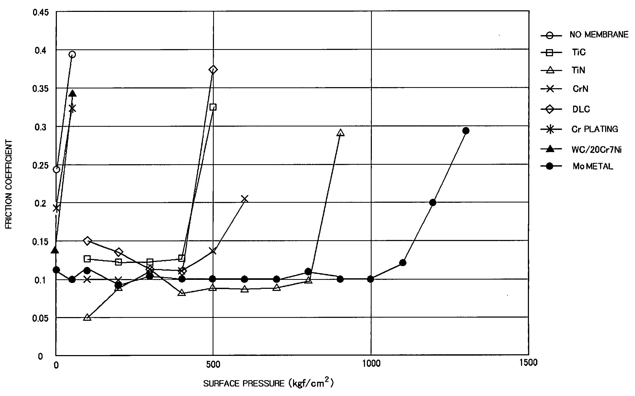
[0167] [Bearing Test 1: Evaluation of Various Hard Membrane of Multi-layer Bearing Axis]

[0168] In this example, a bearing test was conducted between various multi-layer bearing axes obtained by performing induction hardening and tempering (180° C.×1 hr, surface hardness: HRC 60) on the outer circumferential surface of a S55C bearing axis, and the bearing bushing (S45C ingot material) shown in FIG. 15, to check seizure resistant limit surface pressure of the various hard membrane materials. The above-mentioned various hard membranes are in total seven materials of TiC, TiN, CrN, DLC (diamond like-carbon), Cr plating, WC20Cr7Ni and Mo metal. On the inner circumferential surface (contact surface) of the bearing bushing, an induction hardening and tempering (160° C.×1 hr) treatment was performed, and the hardness of the inner circumferential surface was controlled to Hv600 (HRC 55). In this bearing test, various multi-layer bearing axes were swung at an average slipping speed...

example 2

(EXAMPLE 2)

[0172] [Bearing Test 2: Investigation of Alloy Phase in Thermal Spray Membrane]

[0173] In this example, Cu-10Sn, Cu-30Zn, Cu-63Zn, Fe-0.6C-7Al-22Cu alloy and Fe20Ni10Al alloy powder were compounded in amounts of 95, 90, 80, 70, 50, 20 and 5 wt %, in addition to Cu and Ni metals, into Mo metal to prepare a thermal spray mixed powder which was thermal-sprayed on the same bearing axis as in Example 1 to form a thermal spray membrane having a thickness of 0.2 mm. Various multi-layer bearing axes were thus obtained of which surface roughness had been controlled to 3 μm or less. 0.7 wt % of a graphite powder (average particle size: 6 μm, Ronza KS6) was mixed with a 4600 iron powder of #100 mesh or less to obtain a mixed powder, to this was added and mixed an organic lubricant (Acrawax) in an amount of 0.7 wt % and the mixture was molded under a molding pressure of 5 ton / cm2, then, subjected to vacuum sintering at 1150° C. for 2 hours, quenching with N2 gas, and a tempering treat...

example 3

(EXAMPLE 3)

Constant Speed Friction Wearing Test

[0175] In this example, the various thermal spray membrane materials handled in Example 2 in which the amount of the Mo metal phase was 3, 5, 10, 20, 30, 40 and 100 wt % in a Cu-10Sn alloy were thermal-sprayed on a contact surface of a specimen shown in FIG. 19, and the seizure resistance of the various thermal spray membrane materials was checked under a dropping lubrication condition by a constant friction wearing tester. Regarding the sliding test conditions, a carburization quenching and tempering treatment was performed on SCM415, and the surface hardness was controlled to HRC 60 and the surface roughness was controlled to 3 μm or less. Thus prepared rotation disc was rotated at a circumferential speed of 10 m / sec, while #10 engine oil heated at 60° C. was dropped at a rate of 5 cm3 / min on the front surface of the sliding specimen to lubricate this. During this procedure, the friction coefficient and the worn amount at this moment...


PUM

PropertyMeasurementUnit
surface pressureaaaaaaaaaa
kinematic viscosityaaaaaaaaaa
surface pressureaaaaaaaaaa

Abstract

To provide a thermal spray membrane contact material, contact member and contact part and an apparatus to which they are applied, showing excellent seizure resistance and wear resistance even under high surface pressure/low speed sliding, high speed/high temperature sliding, or high surface pressure/high speed sliding. In a bucket connecting apparatus connecting an arm and a bucket by a work implement connecting pin, the above-mentioned work implement connecting pin comprises a base material made of steel having an axis function and a contact surface formed of a thermal spray membrane contact material film-formed on the base material, said contact surface being placed at least on a supported surface site of the work implement connecting pin relative to a bracket and on a slipping contact surface with a work implement bushing, further, said thermal spray membrane contact material being composed of a Mo metal phase, or 10 vol % or more of a Mo metal phase and a metal phase and/or alloy phase containing one or more elements selected from the group consisting of Fe, Ni, Co, Cr, Cu and Zn.

Description

TECHNICAL FIELD [0001] The present invention relates to a thermal spray membrane contact material, contact member and contact part, and an apparatus to which they are applied, intending improvement in seizure resistance and wear resistance, and the like under severe sliding conditions such as high surface pressure / low speed sliding, high speed / high temperature sliding, high surface pressure / high speed sliding, and the like. BACKGROUND ART [0002] Conventionally, as bearings usable with a long period of greasing interval or without greasing, oil-containing slip bearings prepared by allowing pores in a Cu-based or Fe-based porous sintered alloy to contain a lubricating oil are widely put into practical use. Selection of the Cu-based or Fe-based porous sintered alloy is determined depending on conditions such as oil lubricating state, sliding speed, contact surface-pressure and the like, and under light-load and high-speed sliding conditions, a bronze-based oil-containing slip bearing i...

Claims


Application Information

Patent Timeline
Patent Type & Authority Applications(United States)
IPC IPC(8): E02F3/38C22C9/01C22C9/02C22C9/04C22C18/00C22C18/02C22C18/04C22C19/00C22C27/04C22C32/00C23C4/04C23C4/06C23C28/00C23C30/00E02F9/00F01L3/08F02B39/00F03C1/06F04B53/00F16C33/12
CPCC23C4/06Y10T428/12063F16C11/02F16C23/04F16C33/10F16C33/102F16C33/12F16C2360/24Y10S384/912Y10S428/937Y10S384/913Y10T428/12486Y10T428/12826Y10T428/12174Y10T428/12014Y10T428/12479C23C30/00C23C22/12C23C22/18F16C2350/26B22F1/00C22C27/04C23C4/04
Inventor TAKAYAMA, TAKEMORIOHNISHI, TETSUOOKAMURA, KAZUO
Owner KOMATSU LTD
Why Eureka
Try Eureka