
Non-isothermal method for fabricating hollow composite parts

Inactive Publication Date: 2005-11-24
KRUSE CHRISTIAN +3
View PDF15 Cites 64 Cited by
  • Summary
  • Abstract
  • Description
  • Claims
  • Application Information

AI Technical Summary

Benefits of technology

[0016] It is therefore the object of the present invention to provide an improved process for the fabrication of hollow composite parts and vessels.
[0025] Such an improved process enjoys advantages including, as opposed to prior art processes of fabricating hollow composite parts and vessels: reduced cycle times due to the method of assembling the fibre, matrix and bladder prior to insertion into the mould, reduced cycle times due to the method of assembling the fibre, matrix and bladder in the mould, a reduction in the number of manufacturing steps, faster changeover times, faster start-ups, potential labour saving due to less material handling, floor space reduction, adaptability to automation, simplification of material storage and handling, a safer environment for employees, lower training costs, recyclable scrap materials, reduced cycle times from the thermal conditions required for moulding, reduced energy usage from the thermal conditions required for moulding, better distributions of fibers and matrix in the composite, the ability to mould in metallic or polymeric based inserts for connection of additional items to the vessel, the ability to have an integral liner of the same or different polymer to the matrix material of the composite, the ability to tailor barrier properties at the inside of the vessel, the ability to tailor the reinforcing fibre content through the wall thickness of the hollow or vessel component, etc.
[0027] According to another preferential mode of the invention, after step a) before the over-wrapping phase inserts are positioned on the liner, and before step c) the over-wrapped composite is consolidated onto the positioned inserts. Even more preferentially, it is possible to choose the inserts to have an operating temperature such that the critical dimensions are not distorted by the temperature of the heating phase during step c). Additionally, the over-wrapped composite can be locally consolidated onto the positioned inserts.

Problems solved by technology

Hence high processing speeds, notably the application of the thermoplastic matrix based reinforcement to the mandrel, creates a limit on the speed of the process and hence the cycle time.
High drag or friction forces induced by the placement of thermoplastic matrix based reinforcement create further quality problems whereby segregation of the thermoplastic matrix and reinforcing fibres may occur, creating an unfavourable microstructure.
Additionally, the geometry of the component is limited where there is a need to remove the mandrel after processing.
The sequential application of composite layers to the mandrel is known to create high internal stresses in the component, affecting dimensional stability and the eventual durability of the component.
The process cycle time depends on the winding speed and hence this creates a limit on the speed of the process and thereby the cycle time.
High drag or friction forces induced by the placement of thermoset matrix based reinforcement create further quality problems whereby segregation of the thermosetting matrix and reinforcing fibres may occur, creating an unfavourable microstructure.
Additionally, the geometry of the component is limited where there is a need to remove the mandrel after processing.
The cycle time is limited by the need to inject the resin into this space, where pressures are limited where a permanent hollow mandrel is used such that the pressure of the incoming fluid, here the activated resin, does not distort the geometry of the mandrel, hence limiting processes to lower rate and pressure injection rather than the shorter cycle time, high pressure process of structural reaction injection moulding.
Furthermore, the cure reaction of the thermoset matrix either limits the cycle time or, where tailored to occur at a higher speed, induces high stresses in the composite.
Where the mandrel needs to be removed, expensive technologies, such as low melting temperature alloys, must be used where part geometries are not to be impaired.
The cycle time is limited by the need to inject the resin into this space, where pressures are limited where a permanent hollow mandrel is used such that the pressure of the incoming fluid, here the activated resin, does not distort the geometry of the mandrel, hence limiting processes to lower rate and pressure injection rather than the shorter cycle time, high pressure process of structural reaction injection moulding.
Furthermore, the polymerisation reaction of the monomer either limits the cycle time or, where tailored to occur at a higher speed, places limitations on bladder materials.
Where the mandrel needs to be removed, expensive technologies, such as low melting temperature alloys, must be used where part geometries are not to be impaired.
for the bladder assisted moulding process, for the case of thermoset based reinforced material, the need to cure the thermoset matrix material creates problems with chemical attack with rubber-like bladder materials, typically styrene with silicon rubbers, and hence bladder life is reduced.
Bladder materials are generally removable due to the difficulty of achieving a bladder that is flexible enough to enable compaction of the impregnated reinforcing fibres prior and during cure while forming a reliable bond between the bladder and cured composite with the lack of high internal stresses in the finished component.
Cycling the mould temperature is energy inefficient and time consuming, limiting the potential to reduce cycle times, and the fabrication of heated bladder systems is uneconomic for components made in large quantities while also being fragile and of limited life span.
The currently available techniques outlined above have inherent limitations that reduce the potential of the process for applications where a minimum cycle time is required.
Heating the (often metallic) outer mould is both time consuming and requires large amounts of energy.
The use of embedded electrical heaters in a silicon rubber bladder creates a bladder system that is both fragile and difficult to extract from the cooled hollow composite structure or vessel, thereby limiting the geometry of applications.
Furthermore, at the higher processing temperatures required for certain thermoplastics, for example PA12 and PET, the life span of the often costly silicon rubber bladders is limited.
Where the outer layers of the thermoplastic composite are not heated sufficiently above the melting temperature of the thermoplastic matrix, inadequate impregnation occurs, and hence an unfavourable set of mechanical properties results and surface quality is diminished.
Thermosetting materials have additional disadvantages compared with thermoplastic based materials, notably for higher rate production, whereby a limited temperature capability results, unsatisfactory finished product aesthetics, lack of extended durability, lack of appropriateness for recycling and manufacturing related issues such as downtime due to clean-up and material handling costs and sub-ambient storage.
Further, there are environmental concerns arising from worker exposure to vapour, overspray, emissions, etc., encountered during the fabrication process.
Some engineered thermoset resins improve material performance through higher temperature capacity, but unacceptable material costs are associated with them.
Thermoplastic based materials have overcome many of the above problems but the processing techniques available are limited in cycle time due to complex heating and cooling cycles, either of the mould or of expensive and fragile bladder materials and bladders based assemblies with a heating ability.
Additionally, high energy costs are associated with processes that require a cycling of the mould temperature above and below the matrix melting temperature or complex bladder based heating systems.

Method used


Image

  • Non-isothermal method for fabricating hollow composite parts
  • Non-isothermal method for fabricating hollow composite parts
  • Non-isothermal method for fabricating hollow composite parts

Examples


Embodiment Construction

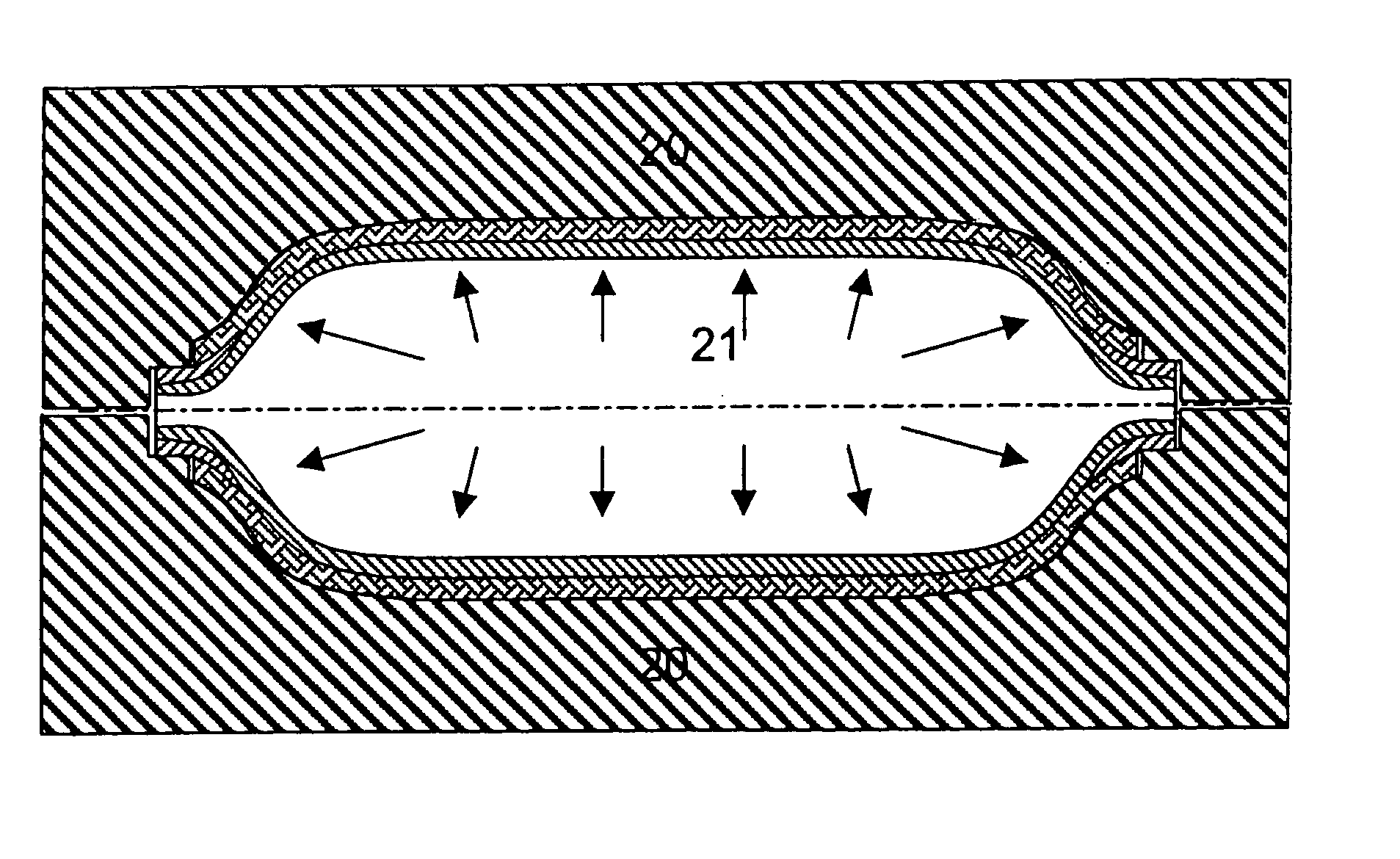
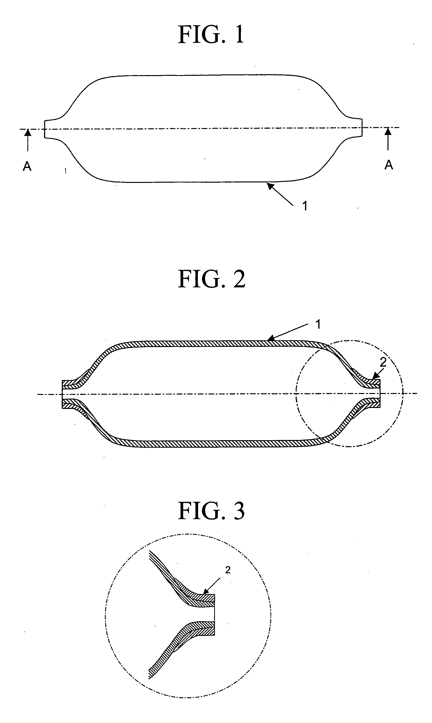
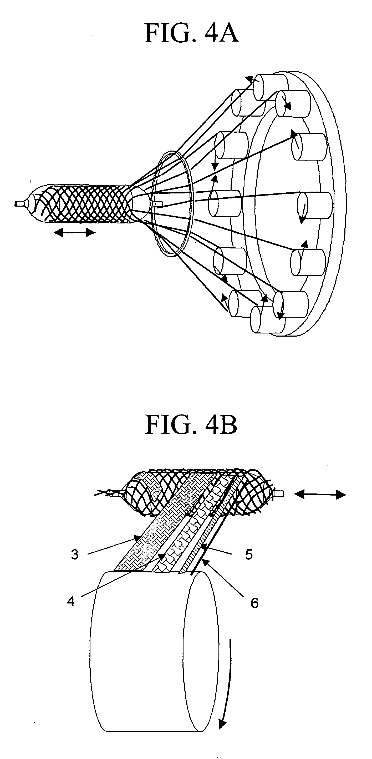
[0052] The first embodiment uses a hollow thermoplastic liner or bladder, produced by processes such as extrusion blow moulding or cast rotational moulding, such as shown in FIG. 1. In the example shown the liner 1 or bladder is generally an elongated structure of geometry such as can be produced via extrusion blow moulding, terminating with either one or more openings, located either on the central axis of the component or at any other suitable location. Hence bladder geometries are not restricted to shapes of revolution, but are applicable to any hollow thermoplastic shape that can be made by processes such as extrusion blow moulding or cast rotational moulding, processes which are well known in the art. In addition to using a thermoplastic liner 1 or bladder, short fibre reinforced or discontinuous fibre reinforced thermoplastic materials may also be used such that the melt viscosity or melt strength of the polymer and fibre mixture is increased both during the extrusion blow mou...


PUM

PropertyMeasurementUnit
Internal pressureaaaaaaaaaa
Temperatureaaaaaaaaaa
Structureaaaaaaaaaa

Abstract

A process for making hollow composite structures or vessels which includes the steps of: A) heating a mixture of thermoplastic matrix and reinforcing fibres wrapped over a rigid or semi-rigid thermoplastic liner or bladder above the melting point of the thermoplastic composite matrix outside of a moulding tool; B) transferring the heated assembly to a mould that is maintained below the melting temperature of the thermoplastic matrix of the composite; C) closure of the mould and application of internal fluid pressure to the liner or bladder to apply pressure to the thermoplastic matrix and reinforcing fibres; D) optionally the use of a special coupling system for rapid connection of the internal pressure; E) cooling of the liner or bladder and thermoplastic matrix and reinforcing fibre assembly in contact with the cold or warm mould while consolidation of the assembly occurs; F) opening of the mould and removal of the finished assembly. Suitable thermoplastic materials for the liner / bladder and thermoplastic composite matrix material include: polypropylene, polyamide, polyethylene, cross-linked polyethylene, polybutylene terephthalate, polyethylene terephthalate, polyoxymethylene, polyphenylene sulfide and polyetheretherketone.

Description

FIELD OF THE INVENTION [0001] This invention relates to the field of fabricating hollow composite parts, especially space frame structures or vessels, and more particularly to improved methods for fabricating space frame structures or vessels and to composite vessels made in accordance with the improved methods. BACKGROUND OF THE INVENTION [0002] Hollow composite structures, or pressure vessels, here referred to as ‘vessels’, such as used to store fluids and solids, particularly under pressure, such as pressurized gas tanks, or more generally in space frame or tubular, load bearing, assemblies have traditionally been fabricated from metals such as steel or aluminium. However, in recent years, the use of composite vessels has become more prevalent. Such vessels are manufactured by a variety of processes, which include filament winding, resin transfer moulding and bladder-assisted moulding. [0003] The technology of filament winding is the process of impregnating dry reinforcing fibres...

Claims


Application Information

Patent Timeline
IPC IPC(8): B29C70/08B29C70/44
CPCB29C70/086B29L2031/7156B29C70/446D04C1/04D04C3/48D10B2505/02B29C70/32
Inventor KRUSE, CHRISTIANMANSON, JAN-ANDERS E.WAKEMAN, MARTYN D.MASKUS, PETER
Owner KRUSE CHRISTIAN
Learn More