
Nanocomposite negative resists for next generation lithographies

a lithography and nanocomposite technology, applied in the field of new high-resolution negative resists, can solve the problems of non-uniform distribution of actual exposure in the pattern writing area, no significant breakthrough, serious intrinsic problem of ebl, etc., and achieve the effects of high contrast, high resolution, and high sensitivity

Inactive Publication Date: 2006-04-27
JUNIVERSITI OF NORT KAROLINA EHT SHARLOTT
View PDF8 Cites 26 Cited by
  • Summary
  • Abstract
  • Description
  • Claims
  • Application Information

AI Technical Summary

Benefits of technology

[0006] The present invention addresses many of the current limitations in next generation lithographic techniques by providing new resists that achieve high sensitivity, high contrast, high resolution and high plasma etch resistance for pattern transfer to a substrate. These goals are achieved through a variety of new resist architectures that incorporate new functional components into resist polymer matrices in novel ways.

Problems solved by technology

However, unlike ion beam lithography, EBL suffers from a serious intrinsic problem, namely electron proximity effects which stem from polymer / electron interactions at the molecular level.
These effects arise from secondary electrons that induce severe degradation of the pattern definition, as the uniform exposure of the resist by the incident electron beam gives rise to a non-uniform distribution of actual exposure in the pattern writing area.
During the past two decades, attempts have been made to decrease the electron proximity effects (see, for example: A. N. Broers, IBM J Res. Develop. 32, 502 (1988)) but no significant breakthrough has been achieved.
A similar intrinsic problem arises using extreme ultraviolet lithography (EUVL at 13.4 nm, or “13 nm” Lithography)), viz. the generation of photoelectrons in the polymeric resist.
Moreover, outgassing can accompany line edge roughness and plague other EUV resists.
Further, the transparency of commercial resists to the 13 nm radiation is far from ideal.
Currently available resists are characterized by a serious lack of transparency to the 157 nm radiation.
Some prototype resin formulations, while offering good transparency, lack the necessary etch resistance to achieve the desired dimension tolerances and positioning accuracy.

Method used


Image

  • Nanocomposite negative resists for next generation lithographies
  • Nanocomposite negative resists for next generation lithographies
  • Nanocomposite negative resists for next generation lithographies

Examples


example 1

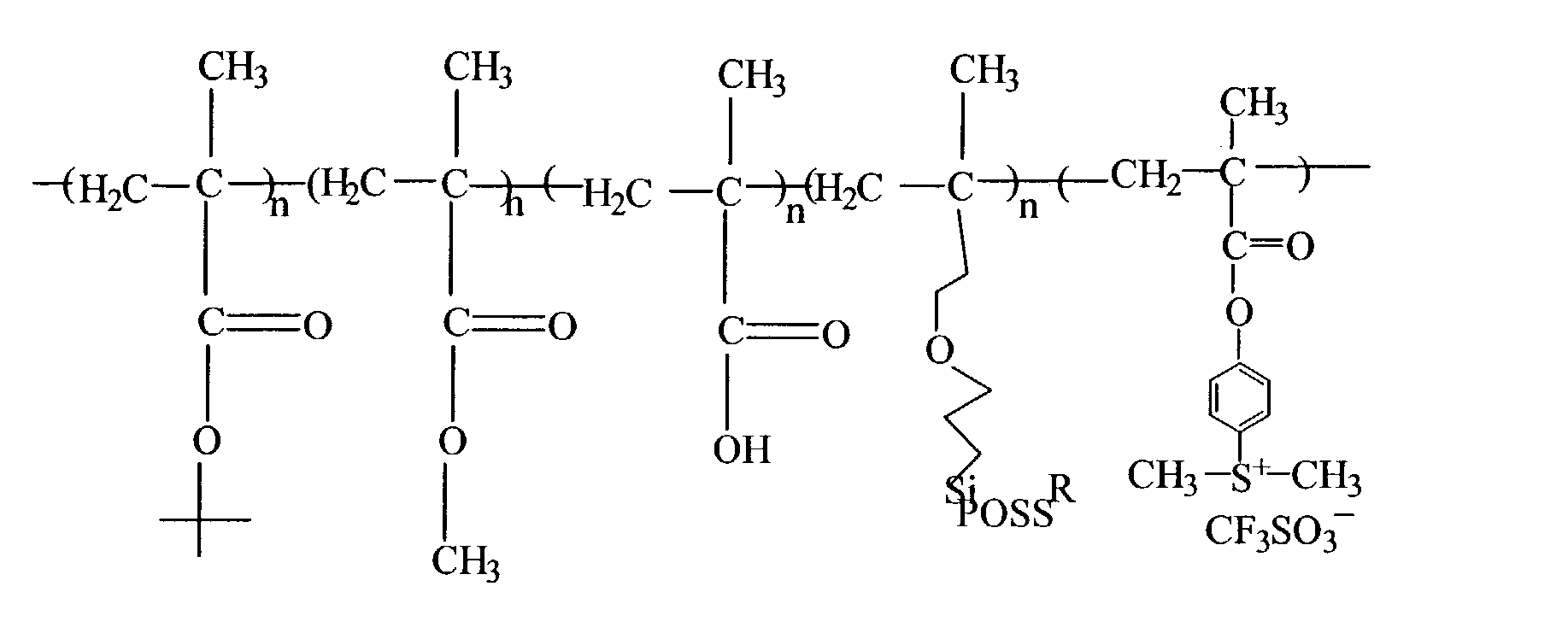
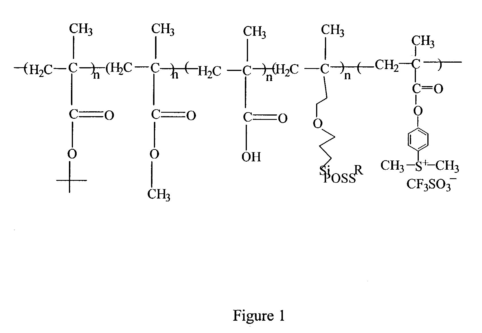
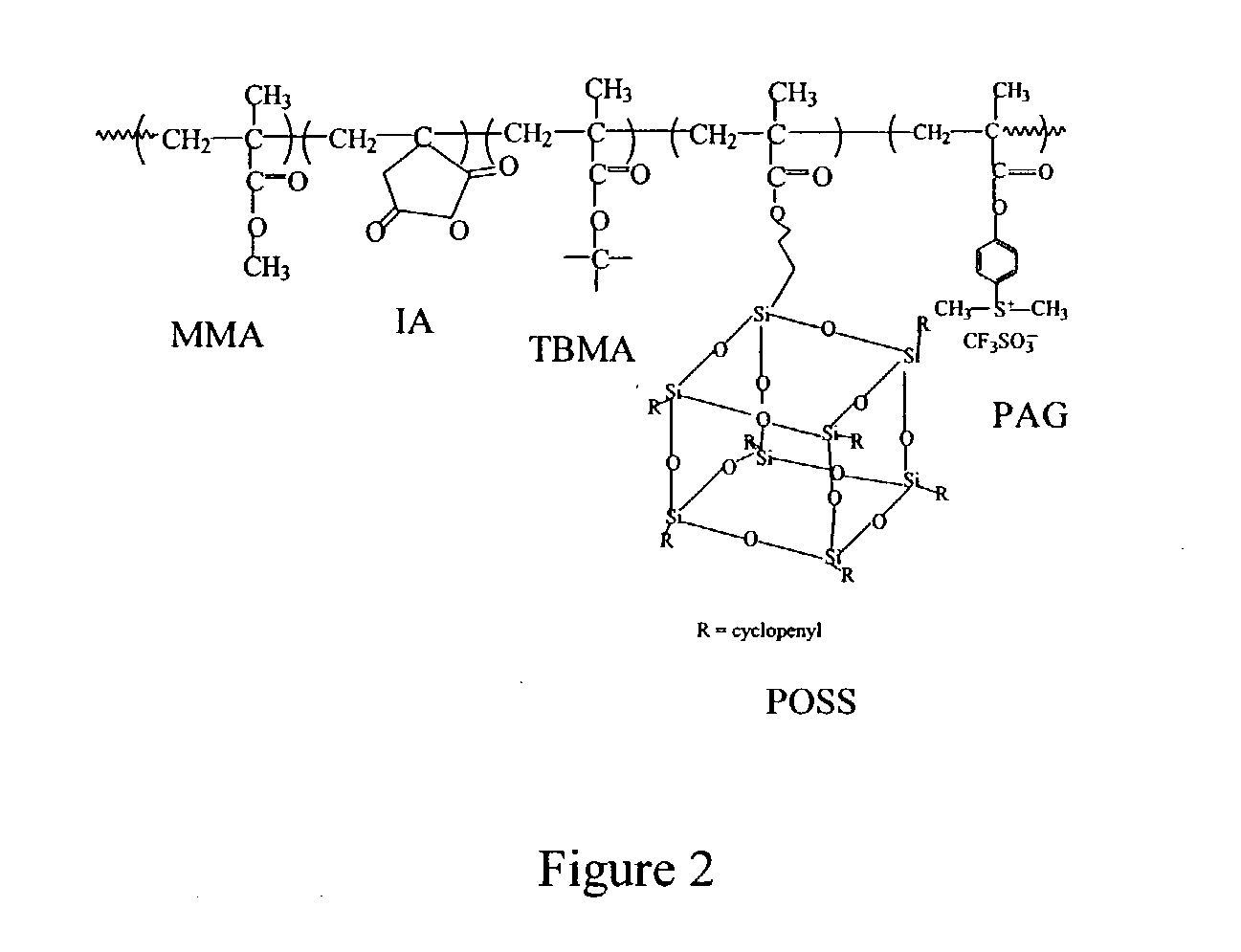
Preparation of a Methacrylate-Based CA Resist Incorporating a Polyhedral Oligosilsesquioxane (POSS)

[0092] All monomeric components used in the polymer preparation were purchased from Polysciences (Warrington, Pa.) or Aldrich (Milwaukee, Wis.). The liquid monomers, tert-butyl methacrylate (TBMA), methyl methacrylate (MMA), and methacrylic acid (MAA) were vacuum distilled under nitrogen prior to use. The inhibitor-free polyhedral oligosilsesquioxane, 3-(3,5,7,9,11,13,15-heptacyclopentylpentacyclo-[9.5.1.13,9.15,15.17,13]octasiloxane-1-yl)propyl methacrylate, abbreviated propyl methacrylate POSS, (Aldrich) was used as received. Tetrahydrofuran (THF) was distilled from sodium and benzophenone under nitrogen. Hexane was reagent grade and used as received. α,α-Azobis(isobutyronitrile) (AIBN) was recrystallization twice from methanol prior to use. Polypropylene glycol methyl ether (PGME) was obtained from Aldrich and used as received. The developer AZ® MIF 300, obtained from AZ Electronic...

example 2

Characterization of a Methacrylate-Based CA Resist Incorporating a Polyhedral Oligosilsesquioxane (POSS)

[0094] The thermal stability of all samples was measured by a Perkin Elmer Thermogravimetric Analyzer 7 (TGA). TGA samples were heated at a rate of 20° C. / min with an O2 or N2 gas flow rate of 25 cm3 / min. Glass transition temperatures (Tg) were measured by a Perkin Elmer Differential Scanning Calorimeter 7 (DSC). DSC samples were heated at a rate of 20° C. / min. Molecular weights were measured by a Millipore Waters GPC using THF as an eluent and polystyrene calibration standards.

[0095] Polymer compositions were obtained by a combination of 1H NMR and TGA analyses. The 1H NMR spectra were obtained on a Bruker Win-500 NMR spectrometer using acetone-d6 as a solvent. The relative composition of the monomers POSS, MMA, TBMA and MAA in a resulting polymer sample were calculated from the area ratios of their characteristic peaks. These data are presented below in Table 2. In parallel, t...

example 3

Etch Study and Polymer Morphology Characterization of a Methacrylate-Based CA Resist Incorporating a Polyhedral Oligosilsesquioxane (POSS)

[0097] Resist solutions (typically 5-10 wt %) were formulated by dissolving polymer samples, along with 2% by weight (relative to the polymer) of the photoacid generator (PAG) triphenyl sulfonium hexafluoroantimonate, in PGME. The low-POSS samples (<22.5% POSS) were readily soluble in PGME (Polypropylene glycol methyl ether) without heating, while the high-POSS sample (30.5%) must be heated to 40° C. to achieve fast dissolution. The resist solutions were filtered through a 0.2 μm Teflon micro filter to remove any undissolved residue.

[0098] Thin films were spin cast on 3-inch silicon wafers on a Brewer / CEE Model 6000 Wafer Processing Track System using a spinning speed of 1500 rpm and spinning times of 60 sec. The films were then baked on a hot plate at 125° C. for 3 min. After cooling to room temperature, the resist-coated wafer was placed in th...


PUM

PropertyMeasurementUnit
roughnessaaaaaaaaaa
diameteraaaaaaaaaa
glass transition temperatureaaaaaaaaaa

Abstract

The present invention provides new high resolution nanocomposite resists applicable to next generation lithographies, methods of making these novel resists, and methods of using these new resists in lithographic processes to effect state-of-the-art lithographies. New nanocomposite negative resists comprising a photoacid generating component, a styrene component, and an optional polyhedral oligosilsequioxane component are provided. Negative resists of this invention may also contain an optional methacrylate component. This invention and the embodiments described herein constitute fundamentally new architectures for high resolution resists.

Description

STATEMENT OF GOVERNMENT LICENSE RIGHTS [0001] This invention was made through the support of the National Science Foundation (Grant No. DMR 9902944), and the Department of Defense (Defense Advanced Research Projects Agency Grant No. N66001-00-1-8903). The Federal Government may retain certain license rights in this invention.TECHNICAL FIELD OF THE INVENTION [0002] The present invention provides new high resolution negative resists applicable to next generation lithographies, methods of making these novel resists, and new lithographic processes using these resists to effect state-of-the-art lithographies. New nanocomposite resist architectures, particularly new chemically amplified resists that incorporate inorganic moieties and photoacid generating groups are described herein, as representative of new class of organic-inorganic hybrid resists. BACKGROUND OF THE INVENTION [0003] Within the next decade the microelectronic industry will require a lithographic process capable of mass-pr...

Claims


Application Information

Patent Timeline
Patent Type & Authority Applications(United States)
IPC IPC(8): C08G77/24G03C1/735
CPCC08G77/442G03F7/0045G03F7/0382G03F7/0757G03F7/0758Y10S430/143Y10S430/122Y10S430/167Y10S430/106Y10S430/111Y10S430/126Y10S430/115
Inventor GONSALVES, KENNETHALI, MOHAMMED AZAM
Owner JUNIVERSITI OF NORT KAROLINA EHT SHARLOTT
Learn More