Solid Solution Material Of Rare Earth Element Fluoride (Polycrystal And Single Crystal), And Method For Preparation Thereof, And Radiation Detector And Test Device

a technology of rare earth element fluoride and solid solution material, which is applied in the direction of conversion screens, instruments, and active medium materials, etc., can solve the problems of cracks in the cooling course, obstructing the development of novel single crystal materials, and luf/sub>3/sub>in itself being impossible in single crystal growth, etc., to achieve the effect of reducing the amount of cooling water, reducing the melting point, and reducing the amount of electric power

Inactive Publication Date: 2007-11-29
TOHOKU TECHNO ARCH CO LTD
View PDF5 Cites 27 Cited by
  • Summary
  • Abstract
  • Description
  • Claims
  • Application Information

AI Technical Summary

Benefits of technology

[0029] According to the present invention, it becomes possible to grow rare earth fluoride solid solution single crystals, and to utilize the same as a scintillator, a solid-state laser material, and the like. Further, according to the present invention, there have been found out fluoride scintillator crystals each having a performance exceeding BGO and physical properties equivalent to or superior to those of GSO. Further, the crystals each have a lower melting point (˜1,350° C.), thereby allowing expectation of decreased electric-power amount, decreased cooling water amount, and the like for production of the crystals. Moreover, although Pt, Ir, and the like are each usable as a crucible material, it is also possible to use a carbon crucible which is inexpensive as compared with them, thereby also leading to a decreased production cost.

Problems solved by technology

Meanwhile, the other rare earth fluorides (SmF3, EuF3, GdF3, ErF3, TmF3, YbF3, LuF3, YF3, and ScF3) each exhibit primary phase transition (orthohombichexagonal or orthohombictrigonal) at a temperature between a room temperature and each melting point, so that conduction of crystal growth from a melt leads to occurrence of cracks in the course of cooling.
Otherwise, only polycrystals are obtained, thereby considerably obstructing development of a novel single crystal material.
It is particularly regretful for a LuF3 crystal having the highest density, that LuF3 in itself is impossible in single crystal growth from a melt such as by a micro-pulling-down method, a Czochralski method, a Bridgman method, a zone melt method, or an Edge-defined Film-fed Growth (EFG) method, due to the problem of primary phase transition.
Further, since many scintillators are required to be densely arranged in fine and elongated configurations in recent multi-layered and high resolutive systems, important selection factors of scintillators include operability, processability, and cost.
Although Tl:NaI has been most typically used for a scintillation detector by virtue of a higher emission amount at a relatively low cost thereof, improved sensitivities of detectors can not be expected due to the lower density of Tl:NaI and the same is difficult in handling due to deliquescency thereof, so that Tl:NaI has been replaced by Bi4Ge3O12 (BGO).
However, the obtained time resolution was on the order of 400 psec (calculated as about 6 cm of positional resolution), thereby failing to reach usage of a time information for direct imaging, while merely bringing about an improved signal-to-noise ratio and counting rate characteristics.
Also concerning a photomultiplier tube (PMT), there is required an expensive window material in case of transmission of wavelengths near 220 nm, thereby leading to an increased cost of device.
Moreover, BaF2 exhibits a detection efficiency which is significantly inferior to that of BGO such that BaF2 is low in resolving power and sensitivity characteristics, resulting in that development of PET's specialized in TOF types are rarely conducted now.
However, Ce:GSO is problematic, since the same also has a slightly delayed rising-up, positive-hysteresis (property by which a light amount is increased depending on irradiation) relative to radiation, and a strong cleavage property.
In turn, the LSO crystal has problems of increased production and working costs and a deteriorated yield, due to its characteristics such as an excessively higher melting point of 2,150° C., a higher anisotropy in linear expansion coefficients, and the like.
Although there is typically used a metal called iridium (Ir) as a crucible material for melt growth of an oxide single crystal having a higher melting point, temperatures exceeding 2,000° C. are closer to the softening temperature of Ir, so that extremely severe temperature control is required for production of LSO crystal.
In addition, since the usable lifetime of an Ir crucible is also short, extensive costs for recasting crucibles also become a severe burden to manufacturers.
Further, there are required a high-frequency oscillator and a higher output for realizing such ultra-high temperatures, thereby generally increasing a running cost.
Meanwhile, concerning the Ce:GSO and Ce:LSO having been used as scintillator-oriented emission materials, although larger inclusion amounts of Ce acting as an emission element lead to higher emission amounts, inclusion amounts exceeding several % lead to significant concentration quenching, thereby failing to exhibit a scintillator effect.
This phenomenon becomes a cause of changing physical properties such as fluorescence decay time, emission amount, and the like, thereby causing a significant problem upon usage in a PET and the like of a high accuracy specification.
Further, although Pr, Ce, F:Gd2O2S ceramic scintillators described in the patent-related reference 1 are high in emission efficiency, single crystals in practical sizes can not be fabricated while light-transmitting ceramics can be narrowly fabricated.
The light transmittance is about 60% / mm, so that fluorescence emitted in the scintillator does not reach a photodiode in a full amount, thereby deteriorating a sensitivity.
Further, it has a problem of a complicated production process and a higher cost.
However, the patent-related reference 2 fails to describe any concrete combinations of RE and R. Further, only Lu is referred to as RE in its embodiments.
However, the crystal growth from a solution has undesirable features from a standpoint of optical crystal, such as a slower crystal growth rate, inclusion of the flux into the crystal as impurities, and the like.
Further, the emission wavelength of Ce3+ in a cerium-substituted lutetium fluoride crystal of the patent-related reference 2 is 310 nm, which leads to a deteriorated sensitivity in case of adoption of a typical PMT made of quartz.
When it is desired to give importance to sensitivity, there is thus required a specific PMT, thereby also causing a problem of cost.
Moreover, although the cerium-substituted lutetium fluoride crystal has a higher emission wavelength as compared with BaF2, the fluorescence lifetime of the former is 23 nsec, so that usage thereof for a TOF type is difficult.

Method used


Image

  • Solid Solution Material Of Rare Earth Element Fluoride (Polycrystal And Single Crystal), And Method For Preparation Thereof, And Radiation Detector And Test Device
  • Solid Solution Material Of Rare Earth Element Fluoride (Polycrystal And Single Crystal), And Method For Preparation Thereof, And Radiation Detector And Test Device
  • Solid Solution Material Of Rare Earth Element Fluoride (Polycrystal And Single Crystal), And Method For Preparation Thereof, And Radiation Detector And Test Device

Examples


examples 1 to 3

[0101] Table 1 shows fabricating conditions of (Gd1-y, Yy)F3, (Gd1-y, Yby)F3, and (Gd1-y, Luy)F3 single crystals according to Examples 1 to 3 (Nos. 1 to 3).

TABLE 1CompoundStartingOptimumNo.compositionmaterialscomposition1(Gd1−x, Yx)F3GdF3(5N)0.4 ≦ x ≦ 0.6x = 0.2, 0.4, 0.6, 0.8YF3(5N)2(Gd1−x, Ybx)F3GdF3(5N)0.2 ≦ x ≦ 0.6x = 0.2, 0.4, 0.6, 0.8YbF3(5N)3(Gd1−x, Lux)F3GdF3(5N)0.2 ≦ x ≦ 0.6x = 0.2, 0.4, 0.6, 0.8LuF3(4N)

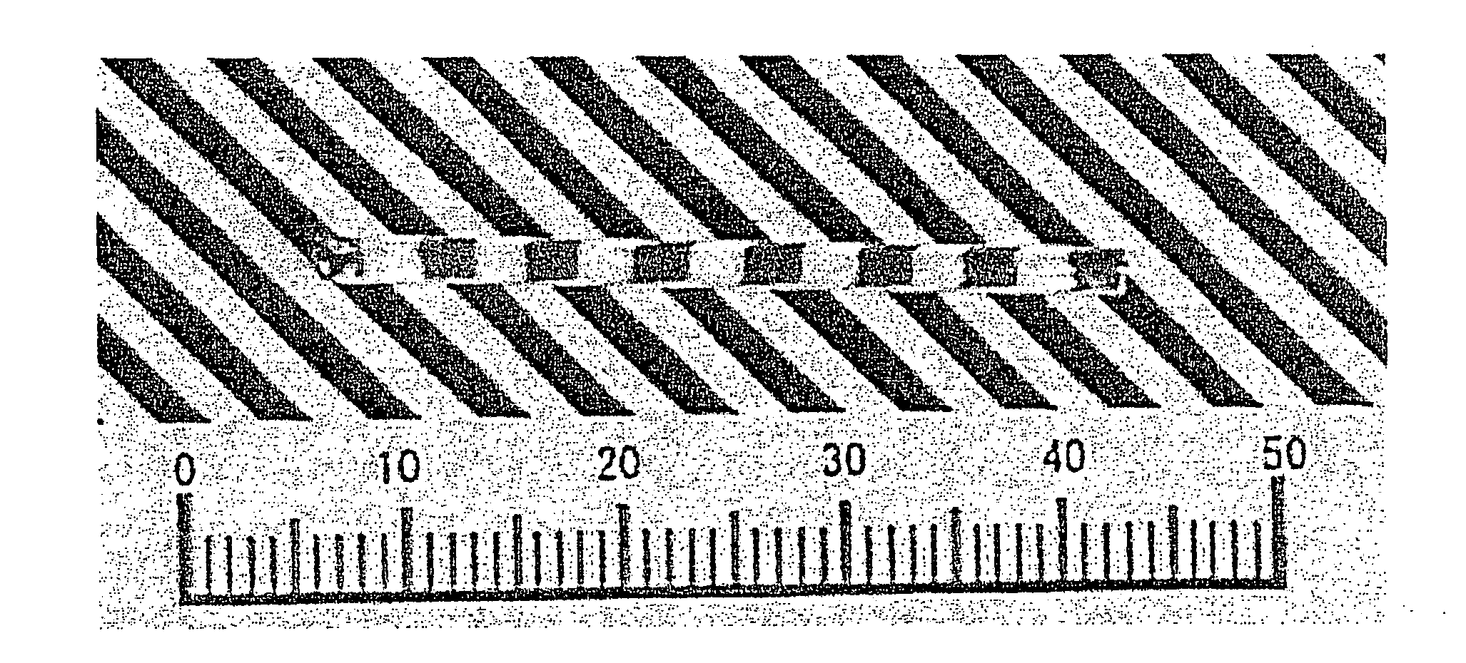
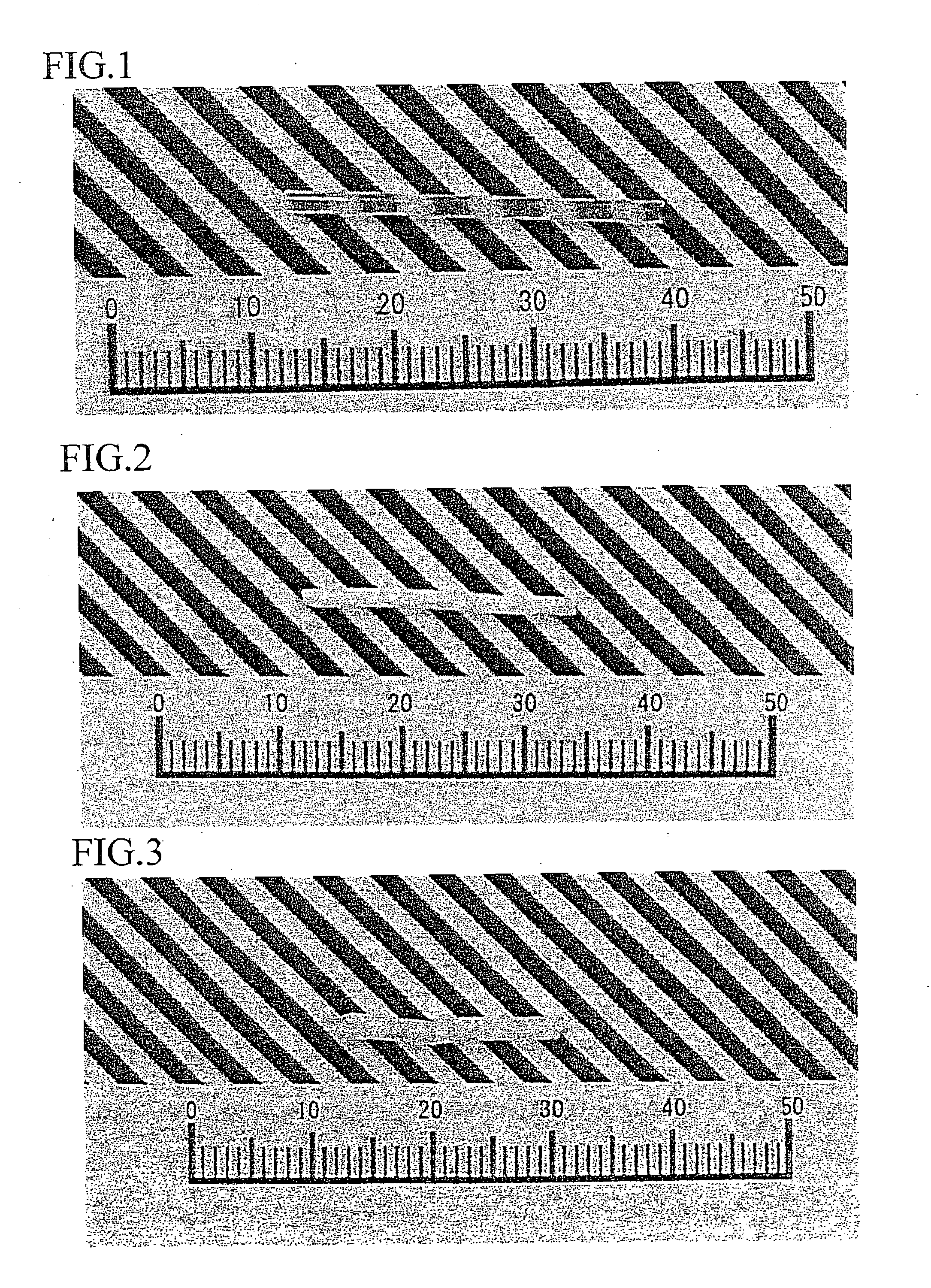
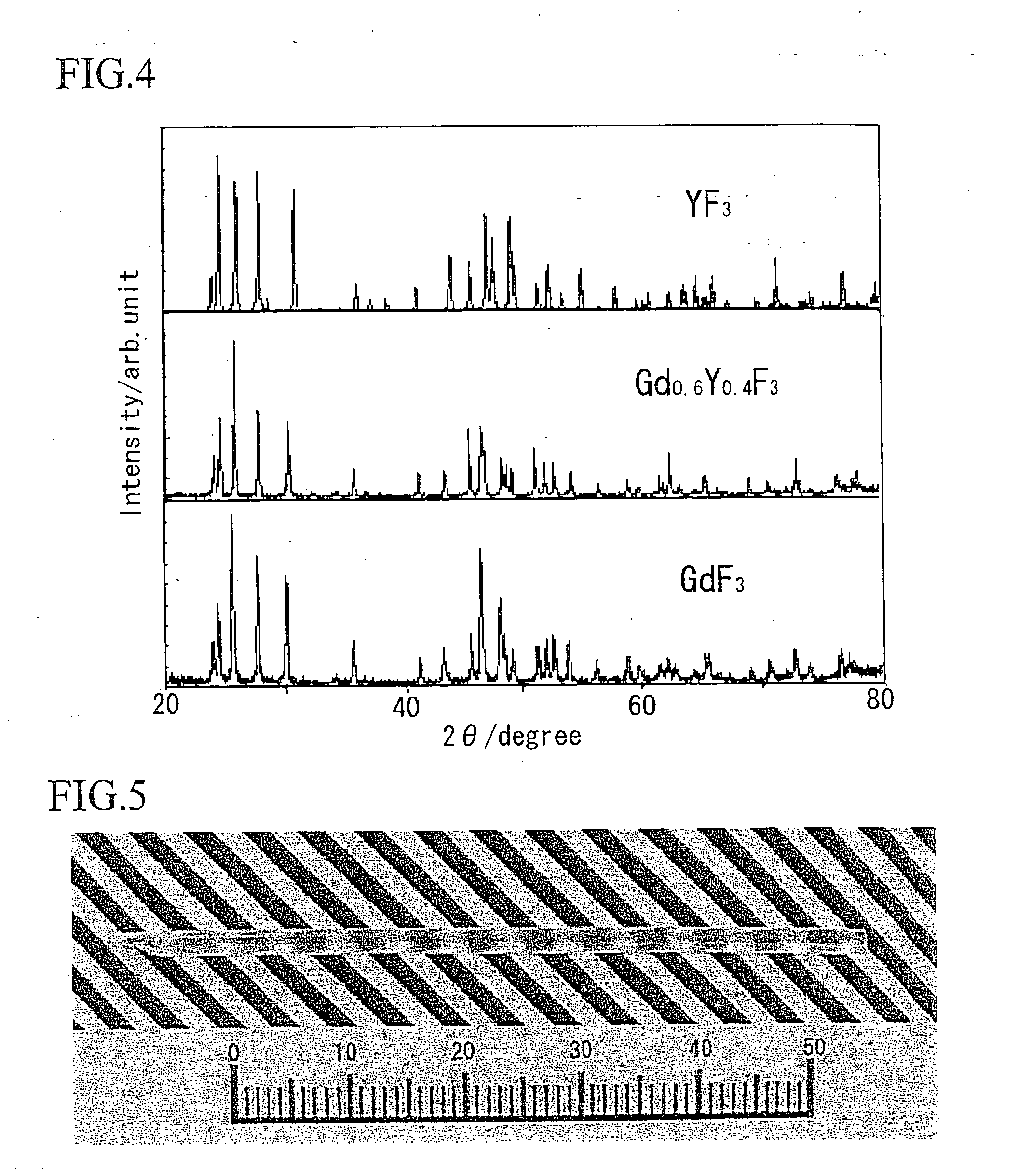
[0102]FIG. 1 shows a photograph of a single crystal represented by (Gd1-y, Yy)F3 (x=0.4). FIG. 2 shows a crystal photograph of YF3, and FIG. 3 shows a crystal photograph of GdF3. It is understood therefrom that although YF3 and GdF3 each exhibit phase transition to thereby lead to cloudy polycrystals, there can be obtained a transparent crystal from (Gd1-y, Yy)F3 (x=0.4). FIG. 4 shows powder X-ray diffraction results thereof. From the powder X-ray diffraction, it is understood that the crystal is a solid solution.

examples 4 to 10

[0103] Table 2 shows scintillation characteristics of Examples 4 to 10 (Nos. 4 to 10).

TABLE 2CompoundCeEmissionEmissionFluorescenceNo.compositionconc.wavelengthintensitylifetimeDensity4(Gd0.6, Y0.39, Ce0.01)F31%300 nm7020 ns6.26 g / cm35(Gd0.6, Y0.37, Ce0.03)F33%300 nm11021 ns6.26 g / cm36(Gd0.6, Y0.35, Ce0.05)F35%300 nm8020 ns6.26 g / cm37(Gd0.67, Lu0.3, Ce0.03)F33%300 nm20020 ns7.43 g / cm38(Gd0.6, Y0.34, Ce0.03, Ba0.03)F33%300 nm22020 ns6.26 g / cm39(Gd0.6, Y0.34, Ce0.03, Sr0.03)F33%400 nm25025 ns6.26 g / cm310(Gd0.4, Y0.27, Lu0.3, Ce0.03)F33%300 nm18020 ns6.67 g / cm3CECeF3100% 300 nm10030 ns6.16 g / cm3

example 11

[0107] There was grown a rare earth fluoride solid solution single crystal represented by MxREyRE′1-x-yFz, (M=Sr, RE=Ce, RE′=GD) based on the micro-pulling-down method.

[0108] Photographs of obtained crystal are shown in FIG. 5 to FIG. 7, which were all colorless and transparent. FIG. 5 shows a solid solution where Gd and Y are included as RE′, and its composition is Sr0.001Ce0.02Y0.529Gd0.45F2.99. In FIG. 6, x0.001Ce0.15Gd0.78F2.93.

[0109] Meanwhile, FIG. 7 shows a crystal as a comparative example where x>0.15, and its composition is Sr0.16Ce0.01Gd0.83F2.84.

[0110]FIG. 8 shows a result where emission characteristics of Sr0.001Ce0.02Y0.529Gd0.45F2.99 and BGO were measured by radioluminescence, and FIG. 9 is an explanatory view of respective emission components in Sr0.001Ce0.02Y0.529Gd0.45F2.99. Further, FIG. 10 and FIG. 11 show results where fluorescence decay times at 380 nm and 290 nm were measured by photoluminescence, respectively.

[0111] From these results, emission near 400 nm...


PUM

PropertyMeasurementUnit
decay timeaaaaaaaaaa
densityaaaaaaaaaa

Abstract

A rare earth fluoride solid solution material (polycrystal and / or single crystal) characterized in that the material is obtained by mutually combining a plurality of rare earth fluorides having phase transitions and having different ion radii, respectively, so that the rare earth fluoride solid solution material is free of phase transitions. A rare earth fluoride solid solution material (polycrystal and / or single crystal) characterized in that the material is represented by (REyRE′1-y)F3 (0.0000<y<1.0000), wherein RE represents one or two or more selected from Sm, Eu, and Gd, and RE′ represents one or two or more selected from Er, Tm, Yb, Lu, and Y. A rare earth fluoride solid solution material (polycrystal and / or single crystal) represented by MxREyRE′1-x-yFz, wherein RE is one or two or more selected from Ce, Pr, Nd, Eu, Tb, Ho, Er, Tm, or Yb, RE′ is one or two or more selected from La, Sm, Gd, Dy, Lu, Y, and Sc, and M is one or more of Mg, Ca, Sr, and Ba.

Description

TECHNICAL FIELD [0001] The present invention relates to a rare earth fluoride solid solution material (polycrystal and / or single crystal), and a production method thereof, as well as a radiation detector and a radiographic inspection apparatus. BACKGROUND ART [0002] Patent-related reference 1: JP-A-5-87934 (87934 / 1993) [0003] Patent-related reference 2: JP-A-2004-137489 [0004] Because of excellent transmissivities over wide wavelength ranges, specific natures, and the like, fluoride crystals have been used as optical materials for optical lithography, crystals for all-solid-state ultraviolet / infrared laser, ultraviolet region window materials, scintillators, and the like. Among them, rare earth fluorides have been widely used as a scintillator, a dopant of an optical fiber amplifier, host and dopant of a solid-state laser material, and the like, by utilizing natures of rare earth elements, and by utilizing Ce3+ in case of CeF3. Further, since rare earth fluoride crystals each have a...

Claims


Application Information

Patent Timeline
Patent Type & Authority Applications(United States)
IPC IPC(8): C09K11/08C09K11/00C09K11/77C09K11/85C30B29/12G01T1/20G01T1/202G21K4/00H01S3/16
CPCC09K11/7719G21K4/00C30B29/12C09K11/7772
Inventor YOSHIKAWA, AKIRAAOKI, KENJISATONAGA, TOMOHIKOKAMADA, KEIFUKUDA, TSUGUO
Owner TOHOKU TECHNO ARCH CO LTD
Why Eureka
Try Eureka