Single crystal diamond elements having convex surfaces and methods of its fabrication

a technology of convex surfaces and diamond elements, which is applied in the direction of manufacturing tools, instruments, lenses, etc., to achieve the effects of low radius of curvature, high accuracy and high quality

Active Publication Date: 2009-01-22
ELEMENT SIX LTD
View PDF2 Cites 13 Cited by
  • Summary
  • Abstract
  • Description
  • Claims
  • Application Information

AI Technical Summary

Benefits of technology

[0023]Accordingly, it is an object of the present invention to provide a method that addresses the problems associated with producing single crystal diamond lenses having spherical surfaces of high quality and low radius of curvature. In particular, it is an object of the invention to produce hemispherical or super-hemispherical surfaces on single crystal diamond suitable for Solid Immersion Lenses (SILs). It is a further object of this invention to provide a method that addresses the problems in polishing single crystal diamond lenses or SILs to a required thickness to within high accuracy. It is a further object of this invention to provide a diamond SIL which, when mounted in a suitable optical system, allows diffraction limited performance to be obtained. It is a further object of the invention to provide a diamond SIL which can be used in a DVD readout system for data readout of high density Digital Versatile Discs (DVDs). It is a further object of the present invention to provide a diamond element having suitable physical properties for use as a tool tip in a metrology system.

Problems solved by technology

Any lens which is used in the manipulation of high intensity laser light needs to have a high optical damage threshold.
Lenses formed from diamond have been made in the past but are rare due to the difficulties involved in polishing such lenses to provide the necessary optical properties.
However, no information is provided as to how a diamond SIL might be produced.
To date, it has not been possible to polish a diamond lens having a sufficiently small radius of curvature, or with the required optical properties, for use as a SIL.
1) Single point turning: In this fairly recent method lenses can be formed of soft materials such as plastics, or infrared transparent materials such as germanium or zinc selenide. Material is removed with a very sharp, very hard turning tool, almost always a diamond tip. By prescribing the motion of the tool tip relative to the workpiece, a surface can be produced on the workpiece with a prescribed shape. This surface need not be spherical but can have an aspheric shape, such as a paraboloid or ellipsoid shape. The accuracy of the shape is mainly determined by the accuracy and stability of the stages on which the turning tool is mounted. Air-bearings are usually used to insulate the work piece and turning tool from vibrations in the environment. This system is not suitable for use in shaping diamond surfaces, because the inevitable wear of the turning tool is much larger than the removal rate of material from the workpiece due to the large ratio of the surface area of the workpiece relative to the area of the tool tip.
2) The more traditional polishing technique for glass optics relies on a polishing powder filled pitch or felt cup or wheel which rotates around its axis. The glass workpiece is pressed onto the cup and is polished by a random motion relative to the cup. Traditional materials used as powders in such polishing include corundum, silicon carbide and diamond. Due to the random motion of the cup or wheel relative to the workpiece, the surface of the workpiece will eventually gain a spherical shape, and very accurate lenses can be produced in this manner. Diamond is traditionally polished using a modified version of this method, but there are limits to the lenses which can be produced in this way, as discussed in more detail below.
This means that in certain planes relative to the crystal axes it is relatively easy to polish diamond, while in other directions polishing is almost impossible by traditional methods.
However, the effects of varying hardness in different directions are still clearly present, and the polishing speed therefore still varies with the orientation of the crystal.
Thus, even when using a resin-bond polishing wheel or cup, the removal rate will be non-uniform across the surface.
This results in a surface having large deviations from the intended ideal spherical shape, especially if a substantial fraction of a hemisphere is required.
However this technique cannot be used for natural single-crystalline diamond, or for synthetic crystals grown using the High Pressure and High Temperature (HPHT) technique.
Furthermore, it is also not appropriate for CVD-grown single-crystalline material.
This is because single crystal CVD diamonds are grown on a substrate which is itself formed from diamond, for which pre-shaping would be just as difficult as for the CVD-grown material to be shaped.
In addition, removing the CVD-grown diamond from the diamond substrate can only be done by sawing or laser cutting, and in any case diamond growth on a curved substrate results in a faceted final stone.
The spherical surfaces of such lenses have radii of curvature much larger than half the diameter of the lens and are thus not suitable for use in SILs (where the radius of curvature is equal to half the diameter of the lens).
In addition, when polishing flat diamond surfaces using traditional techniques, the diamond object is typically gripped in a device known as a “tang” and then manually pressed with considerable force against the surface of the rapidly rotating polishing scaife.
However, no accurate control is available that enables removal of a layer of diamond having a prescribed thickness.
It is therefore not easily possible to control the thickness of the lens to the tolerance required when fabricating a SIL.
When a SIL is used for DVD applications, diffraction-limited performance is required for the optical system including the diamond SIL at short UV range wavelengths, e.g. 405 nm and 266 nm.
However, type IIa natural diamond frequently suffers from large stresses in the material due to a high density of extended crystal imperfections such as dislocations and stacking faults.
Thus, due to stress induced variation in refractive index and stress induced birefringence in the bulk of the diamond material itself, type IIa natural diamond is generally not well suited to make such high quality SILs with diffraction-limited performance.
At best, a very low material yield would result from selecting suitable parts out of type Ia diamonds.
Due to these variations in crystal quality and differences in material properties due to natural variations, such SILs would have to be tested individually and would have individually different dimensions and shapes to compensate for the material's variability, making them unsuitable for mass production and usage.
Currently available tips suffer from the problem of wear, since the tip is in continuous sliding contact with the surface of the object.
Especially when hard and / or rough materials are measured, the wear of the tips leads to rapid deterioration of the spherical shape of the tip.
This leads to measurement errors when using these tips.
This leads to a high cost of measurement caused by the high cost of the tips and the need to recalibrate each new tip.
Another common problem with softer materials such as aluminium is a build-up, even during a single measurement, of the material from which the measurement object is made on the surface of the tip, thus leading to measurement errors.
Metrology tool tips and balls are currently made from hard materials such as tungsten carbide, ruby and sapphire but even these materials show wear.
However the problem of shaping a diamond tip into a sphere or super-hemisphere to the required accuracy has until now precluded its use in this application.

Method used


Image

  • Single crystal diamond elements having convex surfaces and methods of its fabrication
  • Single crystal diamond elements having convex surfaces and methods of its fabrication
  • Single crystal diamond elements having convex surfaces and methods of its fabrication

Examples


examples of embodiments

Example 1

Super-Hemispherical Synthetic CVD-Grown Single-Crystal Diamond SIL with 8-Sided Pavilions

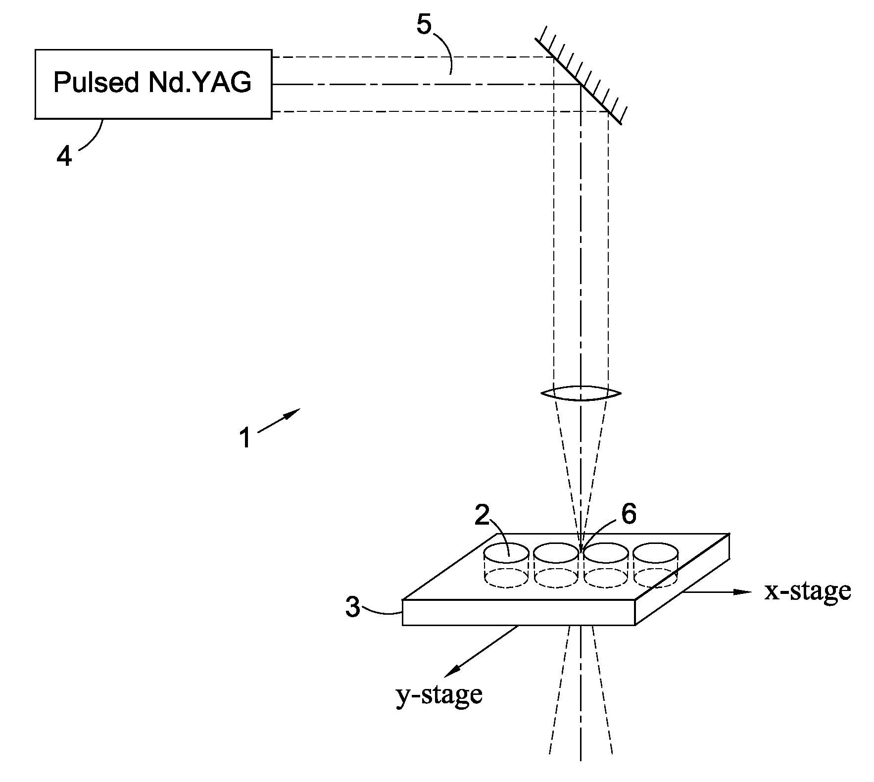
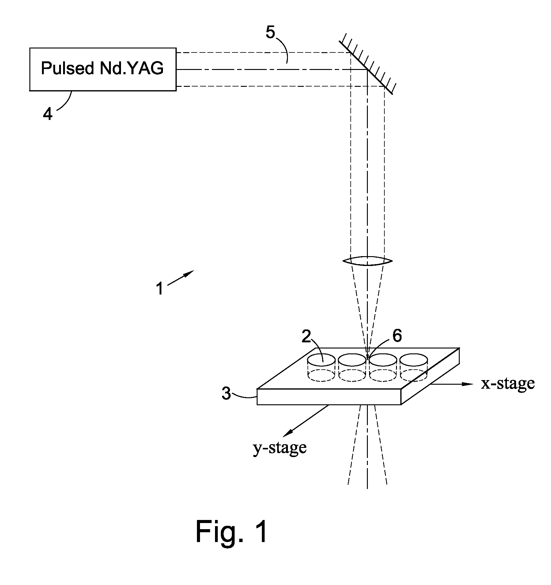
[0126]A super-hemispherical SIL was made from CVD-grown synthetic single-crystal diamond. A CVD grown diamond, approximately 4.5×4.5×3 mm in size, was first sawn into plates of approx. 1.2 mm thick. One plate was then polished flat on one side and mounted onto a graphite carrier plate and placed on an XY translation stage in the focus of a pulsed Nd:YAG cutting laser. Pulse energy was 1.2 mJ in a 150 ns pulse with a pulse repetition rate of 4000 pps (pulses per second). The XY-stage then executed a circular motion with diameter 1.3 mm so that a cylindrical disc was cut out of the plate with diameter 1.3 mm.

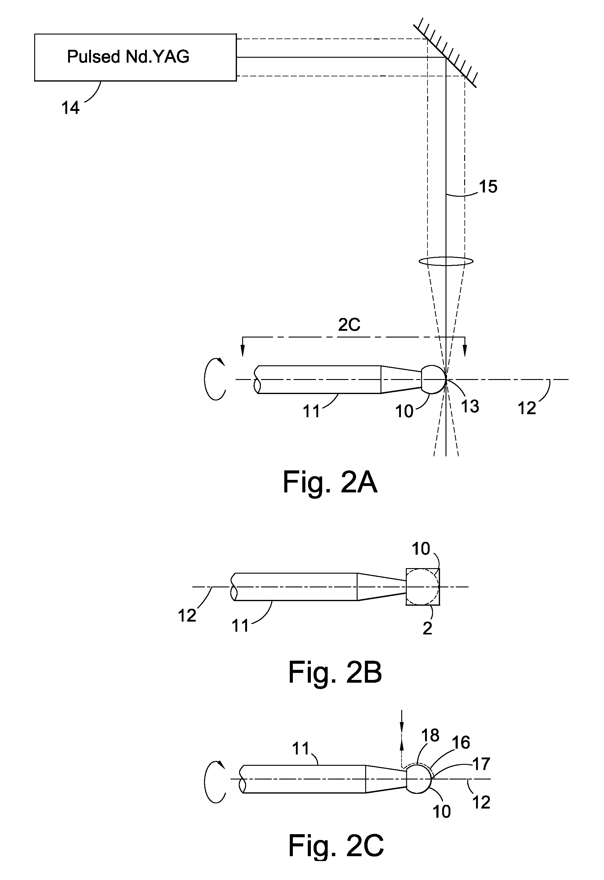
[0127]Subsequently the disc was cleaned to remove any laser residue and brazed with the polished side onto a molybdenum rod which was 20 mm long and 3 mm in diameter with a eutectic alloy of gold and tantalum. The axis had a tapered end such that at the tip where the diamond was solde...

example 2

Hemispherical Synthetic CVD-Grown Single-Crystal Diamond SIL

[0133]A hemispherical SIL was made from CVD-grown synthetic single-crystal diamond. A CVD grown diamond, approximately 3×3×2.8 mm in size, was first sawn into plates of approx. 0.8 mm thick. One plate was then polished on one side and mounted onto a graphite carrier plate and placed on an XY translation stage in the focus of a pulsed Nd:YAG cutting laser. Pulse energy was 1.2 mJ in a 150 ns pulse with a pulse repetition rate of 4,000 pps. The XY-stage then executed a circular motion with diameter 1.4 mm so that a cylindrical disc was cut out of the plate with diameter 1.4 mm.

[0134]Subsequently the disc was cleaned to remove any laser residue and brazed on the polished side onto a molybdenum rod which was 30 mm long and 3 mm in diameter with a eutectic alloy of gold and tantalum. The rod had a tapered end such that at the tip where the diamond was soldered its diameter was 0.8 mm. Prior to brazing the diamond disc was placed...

example 3

Biconvex Natural IIa Type Single-Crystal Diamond Lens of Which One Surface has a Hemispherical Shape

[0139]A hemispherical diamond surface was made from natural type IIa single-crystal diamond. A type IIa diamond, approximately 4 ct in size, was first sawn into plates of approx. 0.95 mm thick. One plate was then polished on one side and mounted onto a graphite carrier plate and placed on an XY translation stage in the focus of a pulsed Nd:YAG cutting laser. Pulse energy was 1.2 mJ in a 150 ns pulse with a pulse repetition rate of 4,000 pps. The XY-stage then executed a circular motion with diameter 1.6 mm so that a cylindrical disc was cut out of the plate with diameter 1.6 mm.

[0140]Subsequently the disc was cleaned to remove any laser residue and brazed with the polished side onto a molybdenum rod which was 30 mm long and 3 mm in diameter with a eutectic alloy of gold and tantalum. The rod had a tapered end such that at the tip where the diamond was soldered its diameter was 1.2 mm....


PUM

PropertyMeasurementUnit
root mean square roughnessaaaaaaaaaa
conical half-angleaaaaaaaaaa
thicknessaaaaaaaaaa

Abstract

A single crystal diamond element having a convex surface is disclosed, the convex surface including a spherical segment for which the maximum peak to valley deviation from a perfect spherical surface is less than about 5 μm. Alternatively or in addition, the RMS deviation from a perfect spherical surface may be less than about 500 nm, or the RMS roughness less than about 30 nm. A single crystal diamond element with a radius of curvature less than about 20 mm is also disclosed. In one aspect a single crystal diamond element having a conical half-angle greater than about 10° is described. The invention also provides a method for forming a rotationally symmetrical surface on a single crystal diamond element, comprising rotating the element about a first axis, applying a laser beam to the element in a direction perpendicular to the first axis, and translating the laser beam in two dimensions in a plane perpendicular to the direction of the beam. If the two-dimensional path follows the arc of a circle a spherical surface may be formed. The invention also provides improving a spherical surface on a single crystal diamond element by pressing a rapidly rotating cup onto a slowly rotating element. The element may be a lens, in particular a solid immersion lens.

Description

FIELD OF THE INVENTION[0001]The present invention relates to the forming of convex surfaces on single crystal diamond elements. In particular, although not exclusively, the invention relates to polishing spherical surfaces on diamond elements for use as lenses, such as solid immersion lenses to be used in information recording and / or reproducing apparatus and in optical pickup devices. Such lenses may also be used in microscopy and lithography and in probes such as endoscopic probes used in diagnostic and minimally invasive surgical procedures in medical applications. The present invention also relates to the polishing of diamond spherical surfaces for use as metrology tips. The present invention further relates to the polishing of diamond spherical surfaces for use as references for measurement of hole diameters or calibration of measurement instruments such as calipers and for use as reference spacers and references that define a plane.BACKGROUND TO THE INVENTION[0002]Lenses have ...

Claims


Application Information

Patent Timeline
Patent Type & Authority Applications(United States)
IPC IPC(8): G02B1/02C01B31/06B23K26/38B24B1/00G11B7/00G02B3/00
CPCB23K26/0039B23K26/0075B23K26/365B23K26/407Y10T428/24479G02B3/00Y10T428/24612Y10T428/24628Y10T428/24355G02B1/02B23K26/0006B23K26/40B23K26/361B23K26/3576B23K2103/50
Inventor NELISSEN, WILHELMUS GERARDA MARIAGODFRIED, HERMAN PHILIPHOUWMAN, EVERT PIETERKRIELE, PAULUS ADRIANUS CORNELISLAMERS, JOHANNES CORNELISPELS, GERRIT JANVAN OERLE, BARTHOLOMEUS MATHIASSPAAY, PAULUS GERARDUS HENDRICUS MARIAMCCLYMONT, MARK ROBINWORT, CHRISTOPHER JOHN HOWARDSCARSBROOK, GEOFFREY ALAN
Owner ELEMENT SIX LTD
Why Eureka
Try Eureka