Micromachined Thermal Mass Flow Sensor With Self-Cleaning Capability And Methods Of Making the Same

a micro-machined, sensor technology, applied in the direction of instruments, liquid/fluent solid measurement, volume metering, etc., can solve the problems of high power consumption, constrained conventional mass flow sensor technology, and often malfunctioning conventional thermal mass flow meters in dirty fluid channels, etc., to achieve robust self-cleaning surface and superior flow measurement performan

Active Publication Date: 2009-06-25
M TECH INSTR HLDG
View PDF36 Cites 34 Cited by
  • Summary
  • Abstract
  • Description
  • Claims
  • Application Information

AI Technical Summary

Benefits of technology

[0014]It is therefore an object of the present invention to provide an apparatus and a method of fabricating a MEMS thermal mass flow sensor with the superior performance in flow measurement while maintaining a robust self-cleaned surface. In the present invention, the porous silicon layer shall be modified to form the acoustic surface wave emitter for the self-cleanin...

Problems solved by technology

Compared to MEMS technology, the conventional technologies of mass flow sensors are constrained by the low flow uncertainties, small turn-down ratio on flow rate measurement, and high power consumption.
In particular, the conventional thermal mass flow meters often become malfunction in a dirty fluid channel such as the fluid flow with smoke or dust in an electrical industrial environment.
The malfunction of the meters lead to interruption of the manufacture and the sensors after liquid or dry cleaning may not have the same performance besides the installation deviations.
However, this type of MEMS thermal flow sensor would have the following limitations:(1) The thin film membrane is very fragile to be damaged and cause the device to malfunction frequently in a dusted or smoked fluid.(2) The opening slots on the surface of membrane are constructed to block the heat conduction horizontally...

Method used


Image

  • Micromachined Thermal Mass Flow Sensor With Self-Cleaning Capability And Methods Of Making the Same
  • Micromachined Thermal Mass Flow Sensor With Self-Cleaning Capability And Methods Of Making the Same
  • Micromachined Thermal Mass Flow Sensor With Self-Cleaning Capability And Methods Of Making the Same

Examples


Embodiment Construction

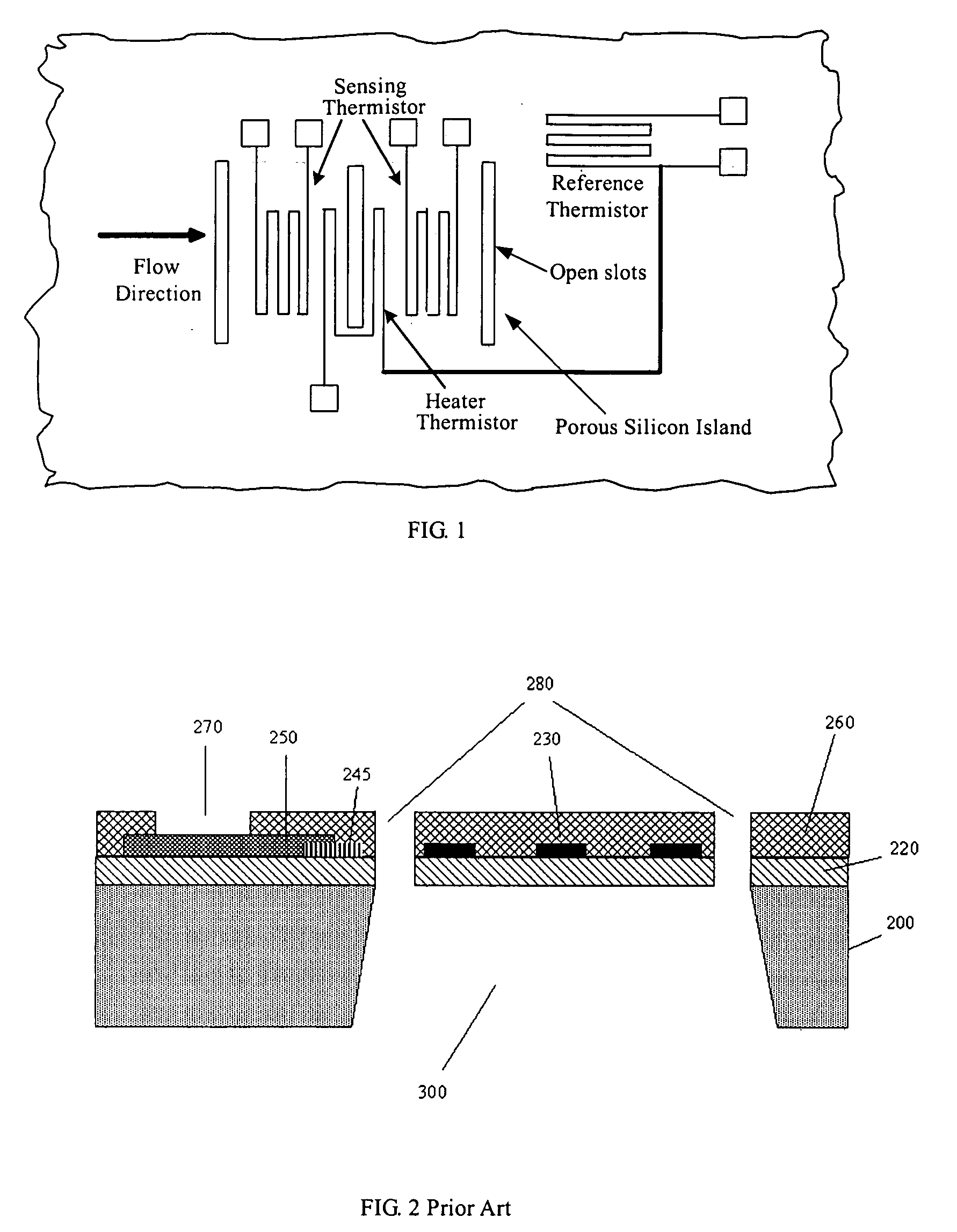
[0028]FIG. 1 illustrates a top view of preferred sensor topology. The reference thermistor is aimed to measure the ambient temperature. The ambient temperature signal provides the feedback to a closed-loop heater thermistor control circuit. The control circuit is designed to keep the heater temperature constantly above the ambient temperature. The upstream and downstream thermistors besides the heater thermistor are worked as temperature sensing elements.

[0029]The working principle behind the fluid speed measurement in a fluid passage is primarily based on anemometry and calorimetry. Since the heater thermistor is operating under constant temperature mode, two major embodiments in the present invention are included:[0030](1) The heater thermistor and reference thermistor are working together as an MEMS constant temperature mode anemometer, which could measure a large dynamic flow rate.[0031](2) The heater thermistor and the two downstream / upstream thermistors comprise a calorimetric...


PUM


Abstract

The current invention generally relates to Micro Electro Mechanical Systems (MEMS) thermal mass flow sensors for measuring the flow rate of a flowing fluid (gas/liquid) and the methods of manufacturing on single crystal silicon wafers. The said mass flow sensors have self-cleaning capability that is achieved via the modulation of the cavity of which the sensing elements locate on the top of the cavity that is made of a silicon nitride film; alternatively the sensing elements are fabricated on top of a binary silicon nitride/conductive polycrystalline silicon film under which is a porous silicon layer selective formed in a silicon substrate. Using polycrystalline silicon or the sensing elements as electrodes, an acoustic wave can be generated across the porous silicon layer which is also used for the thermal isolation of the sensing elements. The vibration or acoustic energy is effective to remove foreign materials deposited on top surface of the sensing elements that ensure the accuracy and enhance repeatability of the thermal mass flow sensing.

Description

BACKGROUND OF THE INVENTION[0001]1. Field of the Invention[0002]The present invention generally relates to thermal mass flow sensors on measuring the flow rate of flowing gas or liquid, more particularly; it concerns mass flow sensors which are made of Micro Electro Mechanical Systems (MEMS) approach and methods of manufacture. The present MEMS flow sensor is built on an active membrane or a porous silicon based device.[0003]The active membrane or the porous silicon device is capable of generating a self-cleaning surface wave, such as ultrasonic acoustic wave emitted from porous silicon, on the active region of sensor surface. With the self-cleaning capability at the time of desire, the sensor itself would be able to work at environments with alien particles or debris from its active region. The sustained cleanness of active area on sensor surface could greatly enhance the flow measuring accuracy and retain its repeatability from calibration.[0004]2. Description of the Related Art[0...

Claims


Application Information

Patent Timeline
IPC IPC(8): G01F1/78B05D1/00
CPCG01F1/6845G01F15/006G01F1/6888
Inventor HUANG, LIJICHEN, CHIH-CHANGYAO, YAHONGWANG, GAOFENG
Owner M TECH INSTR HLDG
Why Eureka
Try Eureka