Interactive Microenvironment System

a microenvironment and interactivity technology, applied in the field of multi-culture microenvironment systems, can solve the problems of inability to reproduce and rigorously deconstruct these parameters, the role of dietary influences in the dynamic interplay between tumor cells and the physical and chemical challenges around them, and the poor resemblance of in vivo topographical richness of culture environment, etc., to achieve the effect of improving alignment, increasing bioactivity, and adding bioactivity

Inactive Publication Date: 2010-10-28
THE OHIO STATES UNIV
View PDF3 Cites 83 Cited by
  • Summary
  • Abstract
  • Description
  • Claims
  • Application Information

AI Technical Summary

Benefits of technology

[0009]Uses of the disclosed nanofiber for cell culturing are varied. Some of such uses include, inter alia, cells can be ‘sorted’ or separated from one another on the basis of motility. This will allow subsequent analysis, for example of genetic differences allowing the development of specific medical treatments. Cutting of nanofiber using a laser or any other energy source allows control over the direction of cell motion. Manipulating or arranging the fibers through magnetic or mechanical means such as AFM tips may produce valuable properties.
[0011]The disclosed nanofiber layers can create in vivo microenvironments via chemical means involving the ‘signaling’ generated by the addition of neighboring cells. Addition of post-spinning bioactivity via applied coatings (e.g., via inkjet printing or the like) or super-critical or sub-critical CO2 treatments to these fibers helps to create valuable biological behavior. Addition of surface treatments to the fibers such as, for example, superhydrophobicity or superhydrophilicity may prove valuable. Addition of a chemotactic source to these fibers helps to guide the cells in a specific direction, usually parallel to the fiber axis. This source may be applied utilizing inkjet printing.
[0012]Conditioning the fibers with culture media and / or cells to add bioactivity can be practiced. The use of any high volatility solvent, such as, for example, hexafluoroisoproponal (HFIP or HFP), acetone, dichloromethane, trifluoroacetic acid, acetic acid, petroleum either, dimethylformamide and others aids in the electrospinning of the aligned fiber arrays. Alignment using a rotating ground or a “split ground” deposition and / or electrostatic focusing methods creates improvements in alignment.
[0013]Different moduli polymer fibers, such as, for example, polycaprolactone, polyethersulfone, or polyethylene terephthalate that may influence biological behavior can be aligned utilizing methods identical to those described earlier. Different polymer blends or core / shell structures to achieve different mechanical properties or biological activity can be practice, such as, for examople, blending polycaprolactone and gelatin to increase bioactivity.
[0018]Generation of three-dimensional tubes of aligned or unaligned fiber allows these desirable biological functions in a manner similar to that of hollow-wall bioreactor technologies. Combinations of this electrospun nanofiber with coatings derived from homogenized whole organs, organ-derived fluids or matrices surrounding specific cells associated with either (a) an organ of interest or (b) a disease of interest. The resulting three-dimensional matrix better recapitulates a specific organ or microenvironment of interest to the point of better targeting aspects of the in vivo microenvironment that correspond to individual patients.

Problems solved by technology

One limitation in cell culture for tissue engineering and other biomedical applications has been the poor resemblance to the topographical richness of the in vivo environment.
However, the role dietary influences play in the dynamic interplay between tumor cells and the physical and chemical challenges around them is uncertain.
Part of the reason is that in vivo systems, and even complex tumor-derived matrices, do not allow for deconstruction of these parameters in a reproducible and rigorous manner.
Conventional 2-D culture distorts tumor cell activity because planar systems are unable to faithfully recapitulate in vivo cell interactions with the surrounding microenvironment.
In contrast to the behavior often observed on TCPS, these ECM-based fibers usually are compliant enough that they do not provide anchorage points for the formation of intracellular stress fibers in motile cells.
The use of conditioned cell media shows considerable promise (1-4) although a lack of standardization, particularly in regards to media age, can make interstudy comparisons difficult.
Unfortunately, prior electrospun fiber does not mimic in vivo cells and cell layers sufficiently to provide the researcher an in vitro model of an in vivo cellular environment.

Method used


Image

  • Interactive Microenvironment System
  • Interactive Microenvironment System
  • Interactive Microenvironment System

Examples


example 1

[0106]A 5 wt-% solution of polycaprolactone (PCL) in 1,1,1,3,3,3-hexafluoro-2-propanol (HFIP) solvent was prepared by continuous stirring at room temperature to dissolve the PCL. The solution then was placed in a 60cc syringe with a 20-gauge blunt tip needle and electrospun using two high voltage DC power sources. One power source was set to −11 kV and connected to a rotating wheel, the other power source was set to +14 kV and connected to the needle. A copper loop then was attached to the needle to focus the fiber towards the wheel. The distance between the needle tip and the wheel was set to 20 cm. Using a digital tachometer to measure the wheel revolutions per minute and knowing the outer diameter, the wheel surface velocity was set to approximately 15 m / s to create aligned fiber or approximately 0 m / s to create random fiber. A syringe pump was used to supply the solution from the syringe at 15 mL / hr.

[0107]Fiber was deposited directly onto the metal surface of the wheel or to a t...

example 2

Multi-Culture Embodiment Utilizing a Transwell® Insert

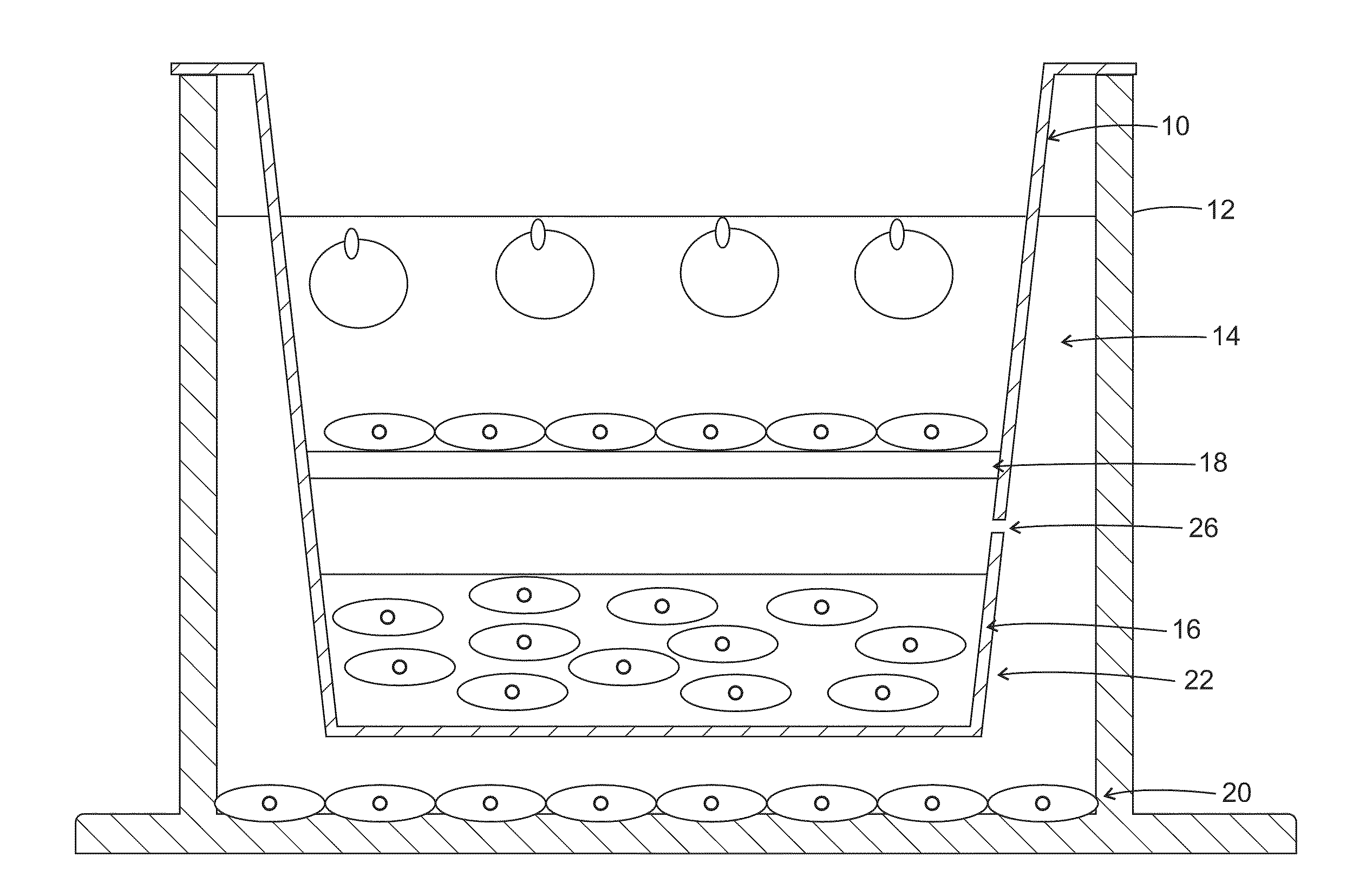
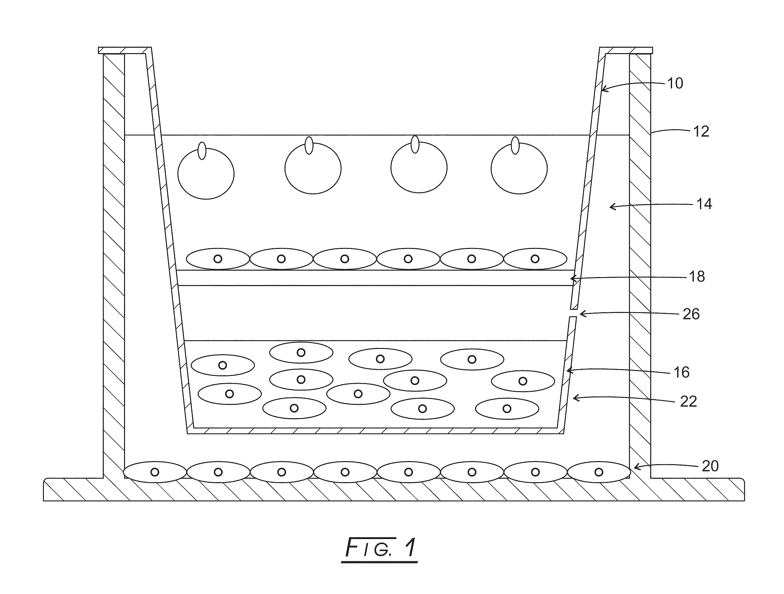
[0108]A commercially available Transwell® insert, like that shown in FIG. 1 or equivalent plate well inserts, may be utilized as a platform for constructing apparatuses useful in various embodiments.

[0109]One of the inherent limitations of standard electrospinning is that it typically produces cell impermeable membranes. Various embodiments overcome this limitation by spinning a high solids content fiber shown to allow full penetration by seeded cells (see references below), providing much higher cell ‘capacity’ than standard, ‘two-dimensional’ electrospun fiber. In this example embodiment, fifteen percent poly(caprolactone) (PCL, MW 65,000; Sigma-Aldrich, St. Louis, Mo.) dissolved in dichloromethane (Mallinckroff Baker, Phillipsburg, N.J.) was electrospun onto an aluminum foil—wrapped 7.6 cm×7.6 cm steel plate at −20 kV with a flow rate of 15 mL / h and a 30 cm tip-to-substrate distance. A voltage of 0 to +5 kV was gradually appli...

example 3

Aligned Fiber in MultiWell Plates

[0127]Random Fiber Preparation

[0128]An 18 wt-% solution of poly(ε-caprolactone) (Sigma-Aldrich, Inc. Mw=65,000) in acetone (Mallinckrodt Chemicals) was prepared by heating acetone to 50° C. followed by continuous stirring to dissolve the PCL. After cooling to room temperature, the solution was placed in a 60 cc syringe with a 20 gauge blunt tip needle and electrospun using a high voltage DC power supply (Glassman) set to 24 kV, a 20 cm tip-to-substrate distance and a 16 mL / hr flow rate. A 3×3″ (7.6×7.6 cm) sheet approximately 100 μm in thickness was deposited onto aluminum foil in 2 minutes. The PCL sheets were then placed in a vacuum overnight to ensure removal of residual acetone. High resolution ESI analysis (Esquire) was used to establish that the resulting acetone content is beneath our ability to detect it (less than 10 ppm) (138). Scanning electron microscopy (SEM) was used to show that, as-deposited, the fibers form a random array (FIG. 11).

A...


PUM

PropertyMeasurementUnit
diameteraaaaaaaaaa
diametersaaaaaaaaaa
diametersaaaaaaaaaa

Abstract

A culture cell for growing animal cells in vitro has sides and a bottom forming a volume. The volume contains a layer of nanofiber upon which animal cells can be cultured. The layer of nanofiber can be oriented or non-oriented. Multiple layers can be placed in the volume, where the layers have different composition and / or different porosity. The nanofiber can be, for example, surface treated or of a core-shell construction.

Description

CROSS-REFERENCE TO RELATED APPLICATIONS[0001]This application claims priority to U.S. provisional patent applications Ser. Nos. 61 / 172,294 filed on Apr. 24, 2009; and 61 / 182,948 filed on Jun. 1, 2009, the disclosures of which are expressly incorporated herein by reference.STATEMENT REGARDING FEDERALLY SPONSORED RESEARCH[0002]The data reported herein was sponsored by National Science Foundation under Grant No. EEC-0425626.BACKGROUND[0003]The present disclosure relates to multi-culture microenvironment systems and more particularly to a cell culture microenvironment system utilizing electrospun fiber, which may be oriented and multi-layered.[0004]One limitation in cell culture for tissue engineering and other biomedical applications has been the poor resemblance to the topographical richness of the in vivo environment. Tumors develop and progress in complex three-dimensional microenvironments in which both normal and cancerous cells encounter specific physical, chemical, and biologica...

Claims


Application Information

Patent Timeline
Patent Type & Authority Applications(United States)
IPC IPC(8): C12N5/071C12M3/00
CPCC12M23/12C12M25/04D01F6/625C12N2533/40D01D5/003C12N5/0068C12M23/34C12M35/04C12M35/08
Inventor LANNUTTI, JOHN J.JOHNSON, JED K.CHIOCCA, E. ANTONIOFISCHER, SARA NICOLELAWLER, SEAN E.LIN, YOUNG C.MARSH, CLAY B.
Owner THE OHIO STATES UNIV
Why Eureka
Try Eureka