

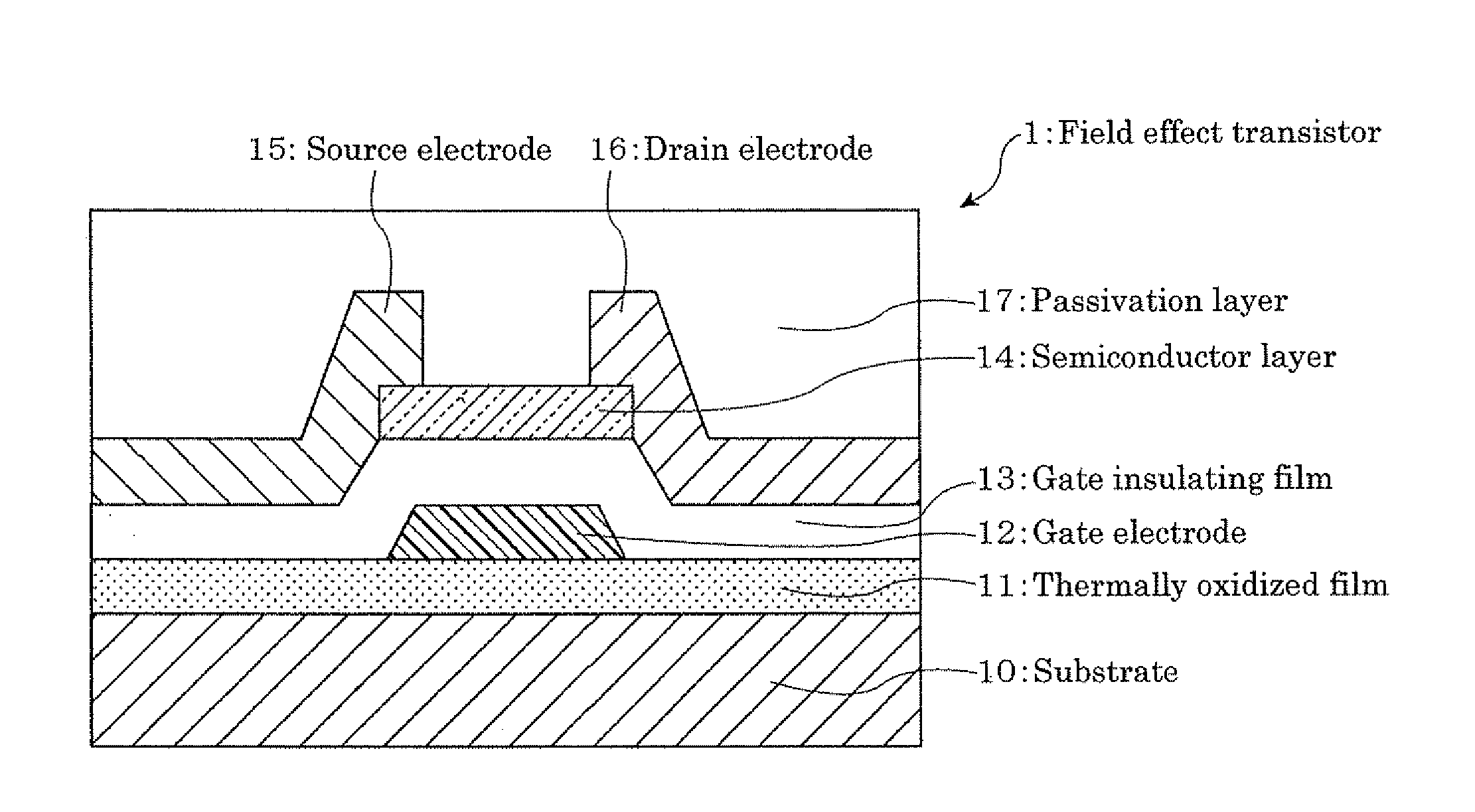
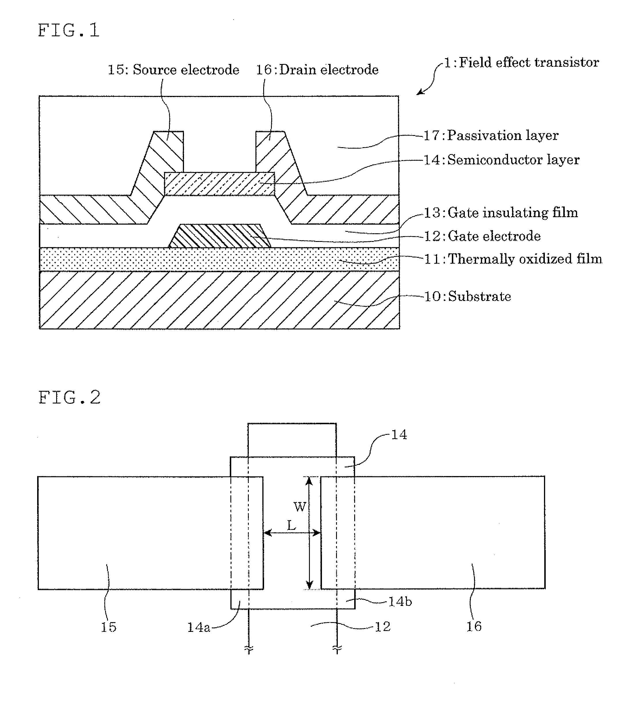
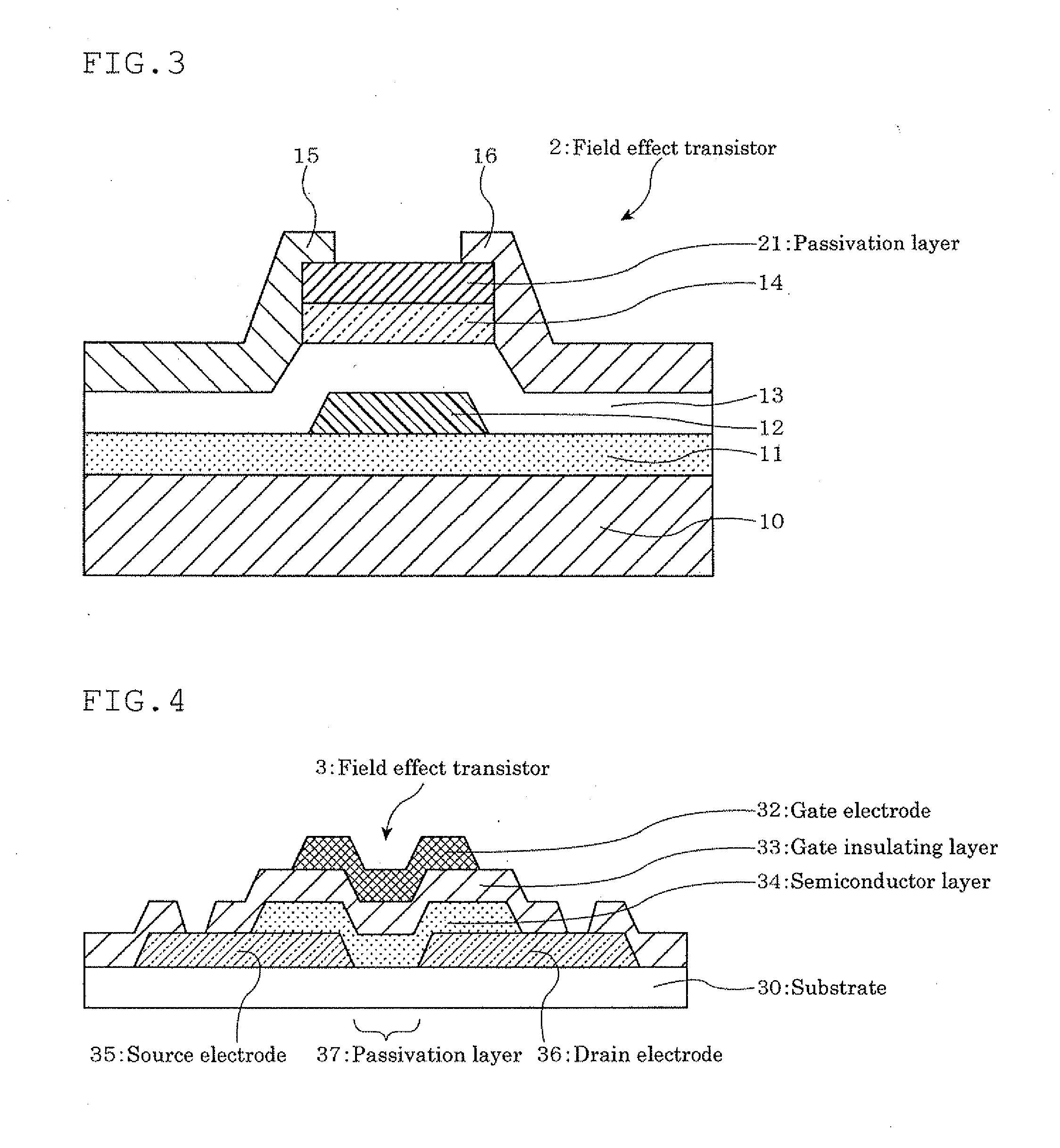
Field effect transistor using oxide semicondutor and method for manufacturing the same
a field effect transistor and semiconductor technology, applied in the direction of transistors, semiconductor devices, electrical equipment, etc., can solve the problems of difficult production of crystalline silicon-based thin films on glass substrates or on substrates formed of organic substances, large amount of energy and a large number of steps, and reduce production costs such as the reduction of the number of masks, so as to reduce contact resistance and increase interfacial strength , the effect of easy production
- Summary
- Abstract
- Description
- Claims
- Application Information
AI Technical Summary
Benefits of technology
Problems solved by technology
Method used
Image

Examples
example 1
A. Preparation of Target I
[0179]As the raw material, 5N (purity: 99.999%) indium oxide (INO04PB, manufactured by Kojundo Chemical Laboratory Co., Ltd.), 5N zinc oxide (ZNO04PB, manufactured by Kojundo Chemical Laboratory Co., Ltd.) and 5N gallium oxide (GAO03PB, manufactured by Kojundo Chemical Laboratory Co., Ltd.) were mixed such that the atomic ratio [In / (In+Zn+Ga)] became 0.42, the atomic ratio [Zn / (In+Zn+Ga)] became 0.42 and the atomic ratio [Ga / (In+Zn+Ga)] became 0.16. The mixture was supplied to a wet type ball mill and pulverized and mixed for 72 hours to obtain raw material fine powder.
[0180]The resulting raw material fine powder was granulated, and press-molded into a size of 10 cm in diameter and 5 mm in thickness. The molded product was put in a firing furnace, and fired at 1500° C. for 12 hours, whereby a sintered body (target) was obtained.
[0181]The target was pulverized and analyzed by inductively coupled plasma emission spectrometry (ICP), the content of impurities s...
example 14
Preparation of Target II
[0222]As the raw material, indium oxide collected from an used ITO target, 5N zinc oxide (ZNO04PB, manufactured by Kojundo Chemical Laboratory Co., Ltd.) and 5N gallium oxide (GAO03PB, manufactured by Kojundo Chemical Laboratory Co., Ltd.) were mixed such that the atomic ratio [In / (In +Zn+Ga)] became 0.42, the atomic ratio [Zn / (In +Zn+Ga)] became 0.42 and the atomic ratio [Ga / (In +Zn+Ga)] became 0.16. The mixture was supplied to a wet type ball mill and pulverized and mixed for 72 hours to obtain raw material fine powder.
[0223]The resulting raw material fine powder was pulverized, and press-molded into a size of 10 cm in diameter and 5 mm in thickness. The molded product was put in a firing furnace, and fired at 1500° C. for 12 hours, whereby a sintered body (target) was obtained.
[0224]The target was pulverized and analyzed by ICP, and it was found that Sn (tin) was contained in an amount of 500 ppm as impurities. The bulk resistance of the target was 3 mΩ an...
examples 15 to 19
Targets III to VII
[0225]Targets were prepared in the same manner as in the preparation of Target II, except that Ge, Si, Ti, Zr or Hf was added in the form of an oxide such that the amount thereof became 500 atomic ppm relative to the total metal elements in the raw material. The quality of the resulting target was almost equivalent to that of Target II, but the appearance thereof was more uniform and excellent as compared with Target II.
[0226]A thin film was formed in the same manner as in B(1) of Example 1, except that Targets II to VII were used. Almost same results as those in Example 1 were obtained when Targets II to VII were used. Further, when continuously discharged for a long period of time, frequency of occurrence of abnormal discharge or the amount of yellow flakes were decreased as compared with the case where Target I was used.
PUM
 Abstract
Description
Claims
Application Information