Selective co methanation catalyst, method of producing the same, and apparatus using the same

Active Publication Date: 2012-03-15
UNIVERSITY OF YAMANASHI
View PDF11 Cites 66 Cited by
  • Summary
  • Abstract
  • Description
  • Claims
  • Application Information

AI Technical Summary

Benefits of technology

[0042]The metal having an oxide reductive capacity can easily reduce the support at low temperature to cause high-activity fine nickel particles to disperse. This mechanism allows the catalyst according to the present invention to show a notably high low-temperature activity. At the same time, the metal having an oxide reductive capacity has a feature of considerably suppressing CO2 methanation reaction, a side reaction in high temperature range. For example, it is observed that the amount of CO2 chemical adsorption decreases in approximate proportion to the support amount of Ru metal. This is for the reason that when the “composite oxide precursor” support is brought into contact with solution of a metal salt having an oxide reductive capacity, metal ions are selectively adsorbed on sites of the support to which CO2 is likely to be adsorbed, which leads to a structural change for inhibiting CO2 chemical adsorption through subsequent reduction treatment, for example.
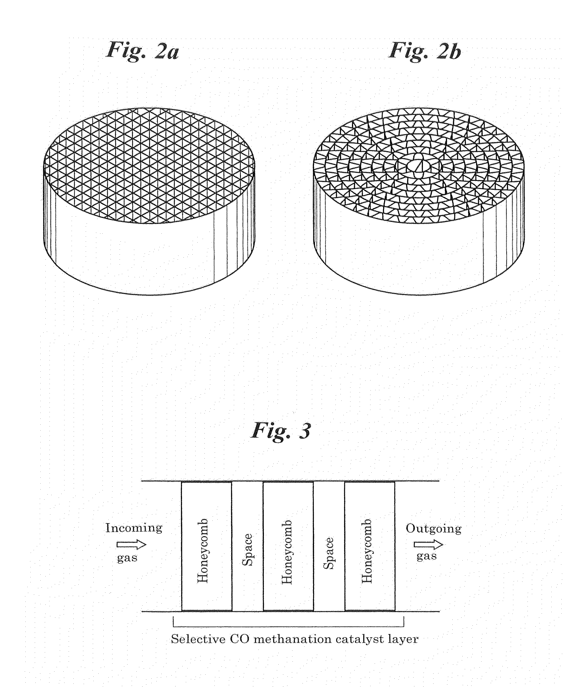
[0043]The foregoing mechanism of “metal having an oxide reductive capacity” (metal which can promote reduction of oxide) with respect to “composite oxide precursor” allows the selective CO methanation catalyst to offer advantages as a material. This material may specifically be formed and processed into, for example, a spherical, cylindrical, or chip-like shape for use. However, if the catalyst is coated and used on a honeycomb base material made of cordierite or metal such as SUS, two mechanisms to be describe hereinafter allow the service temperature range of the catalyst to expand more effectively.
[0044]One of the two mechanisms is based on the fact that the same level of performance can be achieved with the use of an overwhelmingly lower amount of honeycomb catalyst than granular catalyst regardless of what the honeycomb base material is made of. In the case of filling the same volume, honeycomb catalysts can have a larger area of contact with reaction gas than granular catalysts. In addition, for performance reason, the thickness of the catalyst layer coated on the surface of the honeycomb base material is only required to have several hundreds of micrometers. Therefore, the same level or higher performance can be achieved with the use of honeycomb catalysts in an amount ⅕ to 1/10 as low as that for granular catalysts. This offers not only economic but also the great advantage of suppressing the occurrence of hotspots that easily lead to thermal runaway. This is for the reason that honeycomb catalysts exist in

Problems solved by technology

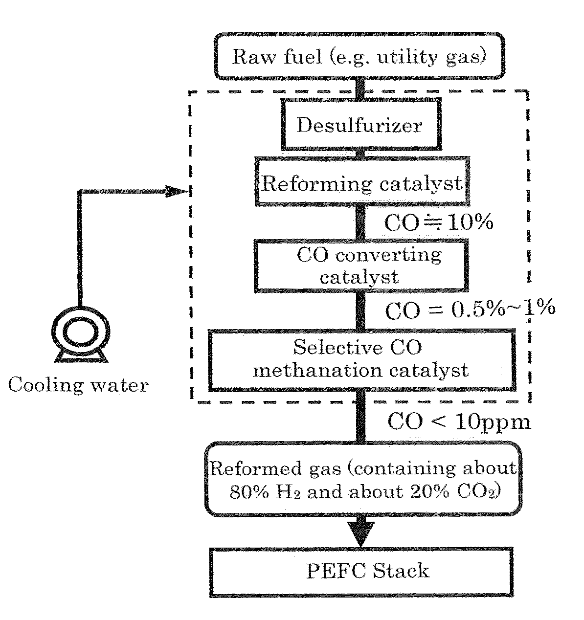
Since polymer electrolyte fuel cells operate at low temperature of around 80 degrees C., if hydrogen rich gas serving as fuel contains carbon monoxide (hereinafter referred to as CO) at a certain level or higher, the anode platinum catalyst undergoes CO poisoning, suffering from a problem of reduction in the power generation capacity and finally making power generation impossible.
Although the CO concentration of gas incoming into a selective CO oxidation catalyst is often designed to be within the range from 0.5 to 1.0%, it is difficult, with the performance of existing selective CO oxidation catalysts, to ensure that the CO concentration is 10 ppm or less throughout the life of the system.
In addition, the rate of CO selection of existing catalysts is not 100% and supplied air (oxygen) is also consumed partially in the oxidation of hydrogen, suffering from an essential problem in that the CO concentration is not lowered sufficiently but hydrogen is wasted.
This selective CO oxidation catalyst multi-staging (doubling typically) technique requires not only double amount of a selective CO oxidation catalyst containing a noble metal, but also an air supply pump, a control system therefor, and further a structure for mixing supplied air and reaction gas homogeneously in each stage, resulting in a significant increase in the cost for accessories, materials, and processing.
This also leads to an increase in the size and capacity of fuel reformers.
Since CO2 exists in hydrogen rich ga

Method used


Image

  • Selective co methanation catalyst, method of producing the same, and apparatus using the same
  • Selective co methanation catalyst, method of producing the same, and apparatus using the same
  • Selective co methanation catalyst, method of producing the same, and apparatus using the same

Examples


first practical example

[0080]As an exemplary technique for synthesizing a composite oxide precursor necessary for preparation of the catalyst according to the present invention, first will be described the low-pressure spray plasma technique.

[0081]In this technique, a low-pressure (high (radio)-frequency) thermal plasma apparatus was used. As raw material solution, 4.67 g of nickel nitrate hexahydrate Ni(NO3)2.6H2O and 17.66 g of aluminum nitrate nonahydrate Al(NO3)3.9H2O were dissolved in 100 mL of distilled water to prepare mixed solution with a Ni / Al molar ratio of 0.34. This mixed solution was sprayed and introduced with argon mixed gas containing 5% oxygen into an argon plasma torch that was fired at an output power of 100 kW and a frequency of 4 MHz in a low-pressure atmosphere apparatus. Powder generated via the plasma torch was collected through a filter. This procedure was repeated until a total weight of 500 g of powder is obtained. The collected powder was dark green fine powder obtained at a y...

second practical example

[0082]This practical example discloses a technique of producing composite oxide precursor powder using a plasma apparatus different from that used in the first practical example. The same raw material mixed solution as the first practical example was used, but the interior of the plasma apparatus was under atmospheric pressure, which was different from the first practical example. The apparatus used included three sections: a raw material solution spraying section, a plasma section, and a particle collecting section. In the raw material solution spraying section, mixed solution of nickel nitrate and aluminum nitrate prepared at the same concentration and molar ratio as in the first practical example was used to generate droplets with a size of 2 to 3 μm using an ultrasonic atomization unit (HM-303N from HONDA ELECTRONICS, Co., Ltd.) and introduced with Ar carrier gas containing 5% O2 into the plasma section. An atmospheric plasma generating apparatus (from ARIOS Inc.) having an outp...

third practical example

[0085]This practical example discloses a preferred technique of producing a composite oxide precursor without using plasma like in the first and second practical examples.

[0086]Solution A prepared by dissolving and stirring 2.0 g of triblock copolymer of a non-ionic surface-active agent P123(EO20PO20EO20) into 20 mL of ethyl alcohol was mixed with solution B prepared by dissolving aluminum isopropoxide (equivalent to 18 mmol of Al element) and nickel nitrate (equivalent to 2 mmol of Ni element) into 3.2 mL of nitric acid and 20 mL of ethyl alcohol, and stirred for five hours at room temperature to obtain a sol. This sol was dried for twenty hours at 60 degrees C. to obtain a gel, and the gel was further heated up to 400 degrees C. at a rate of temperature rise of 1 degree C. / min in a muffle furnace and then kept at the temperature for four hours.

[0087]The thus obtained powder was formed as a mesoporous material having a BET surface area of 350 m2 / g and a pore size of 6.9 nm. Using a...


PUM

PropertyMeasurementUnit
Diameteraaaaaaaaaa
Diameteraaaaaaaaaa
Fractionaaaaaaaaaa

Abstract

Provided is a new catalyst capable of removing carbon monoxide economically without adding particular reaction gas externally. Also provided are a process for producing and an apparatus using such a catalyst. Impregnation of a Ni—Al composite oxide precursor of a nonstoichiometric composition prepared by the solution-spray plasma technique with a ruthenium salt to be supported and performing reduction treatment allows CO methanation reaction to selectively proceed even in the high-temperature range in which CO2 methanation reaction and reverse water-gas-shift reaction proceed preferentially with conventional catalysts. Selective CO methanation reaction occurs reproducibly with another Ni—Al composite oxide precursor or an additive metallic species. Also, the low-temperature activity of CO methanation reaction can be improved through steps different from conventional catalyst production processes in producing such a catalyst material, whereby the temperature window the resulting catalyst material has can be utilized most effectively.

Description

BACKGROUND OF THE INVENTION[0001]1. Field of the Invention[0002]The present invention relates to a catalyst for selectively transforming carbon monoxide CO, which is generated as gas byproduct during production of hydrogen gas from a variety of hydrocarbon fuels such as natural gas, LPG, and kerosene, into methane CH4, a method of producing and an apparatus using such a catalyst. The technique the present invention discloses, with which hydrogen rich gas with a CO concentration of 10 ppm or less can be generated stably and also a catalyst used therefor can be produced at low cost, is suitably applicable to, for example, fuel reformers in home-use power generation systems using a polymer electrolyte fuel cell.[0003]2. Description of the Related Art[0004]Since polymer electrolyte fuel cells operate at low temperature of around 80 degrees C., if hydrogen rich gas serving as fuel contains carbon monoxide (hereinafter referred to as CO) at a certain level or higher, the anode platinum ca...

Claims


Application Information

Patent Timeline
IPC IPC(8): B01J23/755B01J23/89B01J7/00
CPCB01J23/40Y02E60/50B01J35/006B01J35/04B01J35/08B01J35/1019B01J35/1061B01J37/036B01J37/349C01B3/38C01B3/48C01B3/586C01B2203/0233C01B2203/0238C01B2203/0244C01B2203/025C01B2203/0283C01B2203/0445C01B2203/047C01B2203/066C01B2203/1241C01B2203/1258H01M8/0668B01J23/755Y02P20/52Y02P70/50
Inventor WATANABE, MASAHIROYAMASHITA, HISAOHIGASHIYAMA, KAZUTOSHIMIYAO, TOSHIHIROCHEN, AIHUA
Owner UNIVERSITY OF YAMANASHI
Why Eureka
Try Eureka