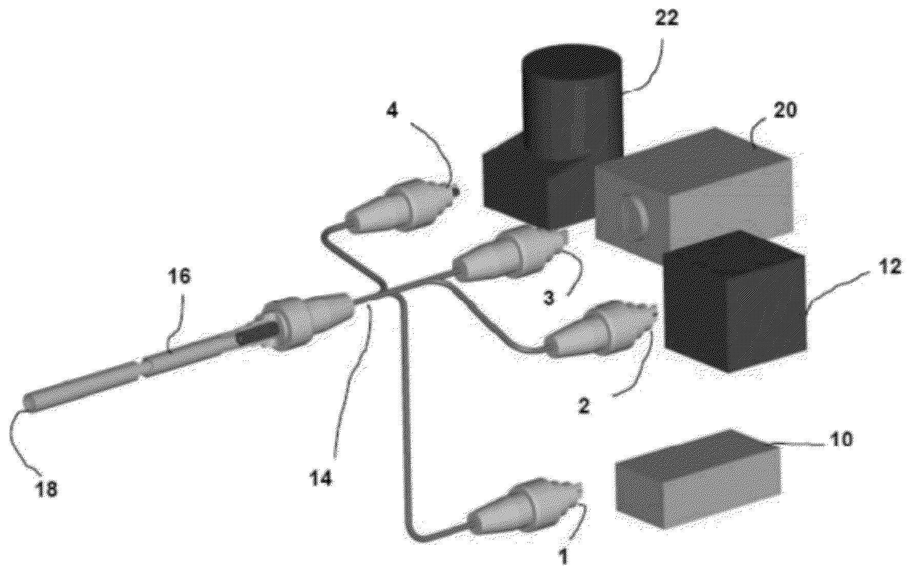
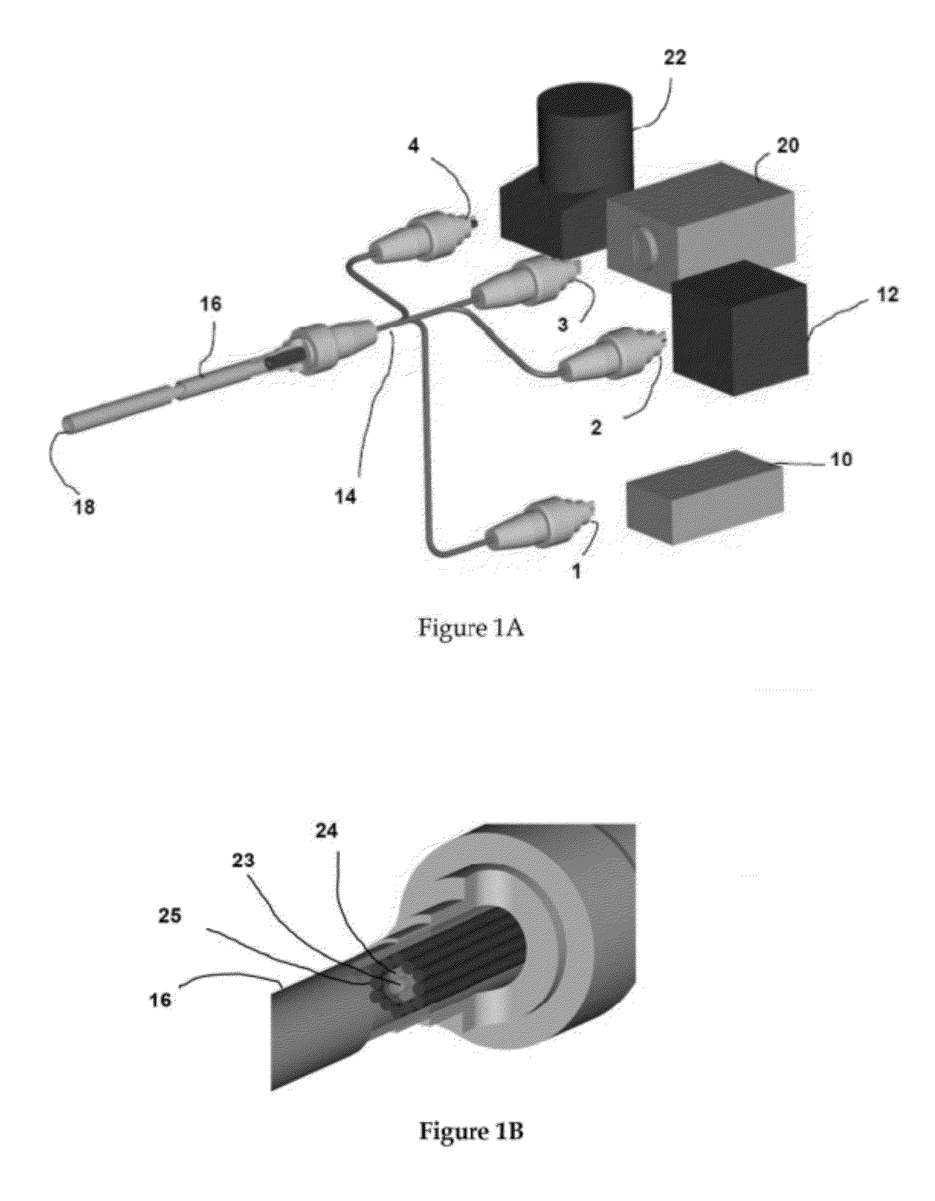
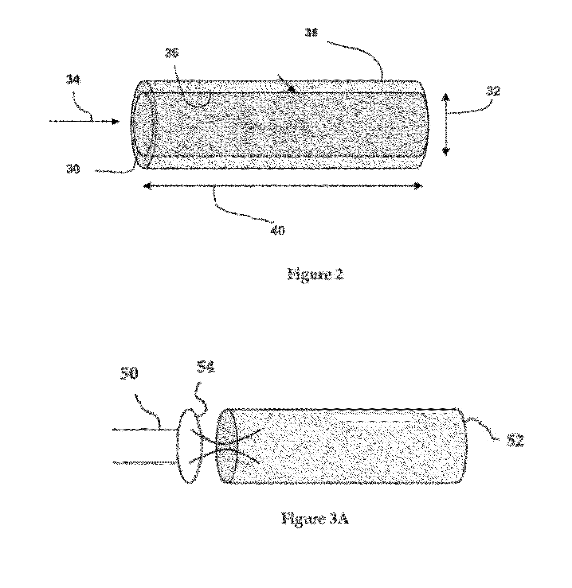
[0008]Objects of the present invention include providing improved techniques for performing integrated IR and Raman spectroscopic measurements on a gas sample located within a confined volume, extending the
path length of a hollow gas sampling structure thereby providing a capability for sensing a broader range of gas species, obtaining complimentary spectroscopic gas species information, reducing the
device form factor and increasing the measurement sensitivity.
[0011]Embodiments of the present invention include a hollow
fiber waveguide (HFW) and a
metal coated capillary, each possibly but not necessarily in combination with a
solid core optical fiber probe which provides robust field deployment. The
optical fiber probe may also encompass an
optical filter(s). The hollow gas sampling structure embodiment, e.g., acts as an extended
optical path length or multi-pass
cell that does not require sensitive alignment. The embodiments using a retro-reflection optical design enhance sensitivity by extending the
optical interaction path length of the Raman excitation light and the IR light with the gas sample and by increasing the number of Raman and IR product (e.g. photons) collected.
[0012]The hollow structures of the present invention function as a fiber optic-based multi-pass
optical cavity to increase the light (e.g.
photon) / gas interaction path length and as a cylindrical gas
cell to confine the gaseous
analyte during the measurement to a known volume essential to quantitative measurements. Both functions combined enable low detection limits to be reached in a
continuous measurement scenario. A variety of spectroscopic techniques can be used with this hollow cylindrical structure in parallel, but not limited to,
Infrared and
Raman spectroscopy by
coupling of light of differing wavelengths. In addition, the inner surface of the hollow structure can be coated with a single or multiple optical coatings (e.g., (but not limited to) reflective metallic and
dielectric layers) optimized to achieve higher
throughput and sensitivity.
[0014]This invention combines Raman and IR
spectroscopy in a
single fiber-based gas sensor device for the purpose of detecting, identifying, and quantifying low concentration levels of individual gases and gas mixtures. This combination of both
Raman scattering and
IR absorption spectroscopy in a single optical design produces complementary spectra that function as molecular-level fingerprints of the gaseous species being probed. Together, these signatures enable the identification of unknown gas species. An essential component of embodiments of this invention include a hollow gas sampling structure in which the gas analytes are confined to a predetermined volume and for increasing the interaction path length between the (excitation) light and the gas molecules. This enables detection limits down to the parts-per-million (ppm) and parts-per-billion (ppb) levels to be reached. Also important to some embodiments is the choice of coatings (e.g., (but not limited to) aluminum, silver,
dielectric, etc.) at the inside of the hollow fiber to minimize optical losses.
Coupling of a
solid core probe or
optical fiber, which delivers excitation light to the hollow structure, is provided by a novel fiber geometry. Important for a
remote sensing geometry is a
double pass arrangement using a retro reflector to direct the
scattered light (Raman) or to further increase the absorption path length of light (IR) traveling back through the hollow structure and into the
solid core fiber probe, enabling detection of the signals at the same side as the excitation.
[0015]The spectroscopic techniques
usable in the present invention include absorption, photo-
acoustics, Raman,
fluorescence, surface-enhanced Raman, surface-enhanced
infrared, and / or coherent anti-Stokes Raman scattering spectroscopy. The hollow structure functions as a confined volume gas sampling structure in which photons from a
light source interact with the gas sample to be detected, and which is present inside the hollow structure. The sample can either be in aqueous or gaseous phase, and can be delivered into the structure by either directly pumping or flowing it into the volume, or by natural
diffusion,
convection, etc. The molecules can be introduced through the ends of the hollow structure, which are open to the surrounding environment. Another embodiment provides porous structures either at specific locations or along the entire hollow gas sampling structure. Some of the hollow structures
usable in the invention are cylindrical in shape and have a
diameter ranging from hundreds of microns to several millimeters and its length can be up to meters long. The inside of the structure can be coated with a light guiding and / or reflecting layer, e.g., (but not limited to) a metallic or
dielectric layer, to enable light to be guided down the length of the hollow structure. The
coating also serves to guide the analytical
signal (e.g., scatterings). The layer can also be functionalized for directly targeting and / or recognizing molecules, or roughened to enable surface-enhancement features. Light, from a source such, but not limited to, as a
quantum cascade laser,
diode laser, or a
broadband source is efficiently coupled into the hollow structure using, e.g., a focusing lens, micro-
optics, fiber optic components, or combinations thereof.


