Catalyst and Method for Synthesis of Carbon Nanomaterials

a carbon nanomaterial and catalyst technology, applied in the direction of catalyst activation/preparation, metal/metal-oxide/metal-hydroxide catalysts, physical/chemical process catalysts, etc., can solve the problems of metal grain particles growing to large sizes, ss does not readily react with gaseous hydrocarbon feedstock, etc., to promote the synthesis of carbon nanomaterials and increase surface roughness

Inactive Publication Date: 2016-12-22
NORTHEASTERN UNIV
View PDF0 Cites 10 Cited by
  • Summary
  • Abstract
  • Description
  • Claims
  • Application Information

AI Technical Summary

Benefits of technology

[0019]Yet another aspect of the invention is a catalyst for synthesis of a carbon nanomaterial. The catalyst is made by the method described above, and contains a steel alloy, such as a stainless steel, that has been heat treated in an oxidative atmosphere at a temperature and duration that breaks down the protective chromium oxide layer of the steel, increases surface roughness, and promotes the synthesis of a carbon nanomaterial by a chemical vapor deposition method.

Problems solved by technology

However, SS does not readily react with the gaseous hydrocarbon feedstock because it has a passive film of chromium oxide on its surface.
However, when they are separated they are either inactive (Mo alone) or unselective (Co alone) [30].
Since most such treatments are conducted for long periods of time, at elevated temperatures, and under oxidative conditions, metal grain particles grow to large sizes under these conditions.

Method used


Image

  • Catalyst and Method for Synthesis of Carbon Nanomaterials
  • Catalyst and Method for Synthesis of Carbon Nanomaterials
  • Catalyst and Method for Synthesis of Carbon Nanomaterials

Examples


example 1

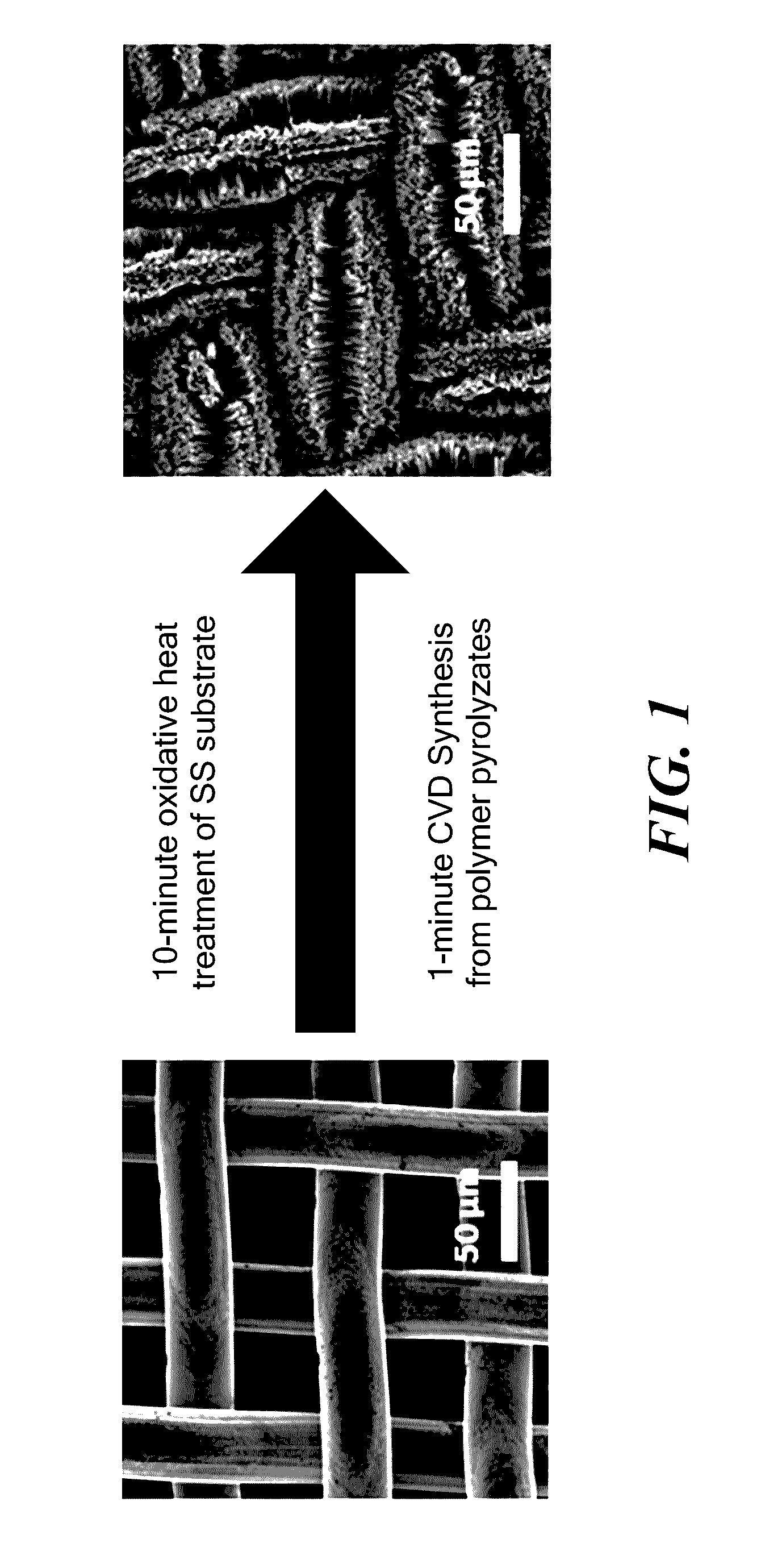
Catalyst Formation by Heat Treatment of Stainless Steel

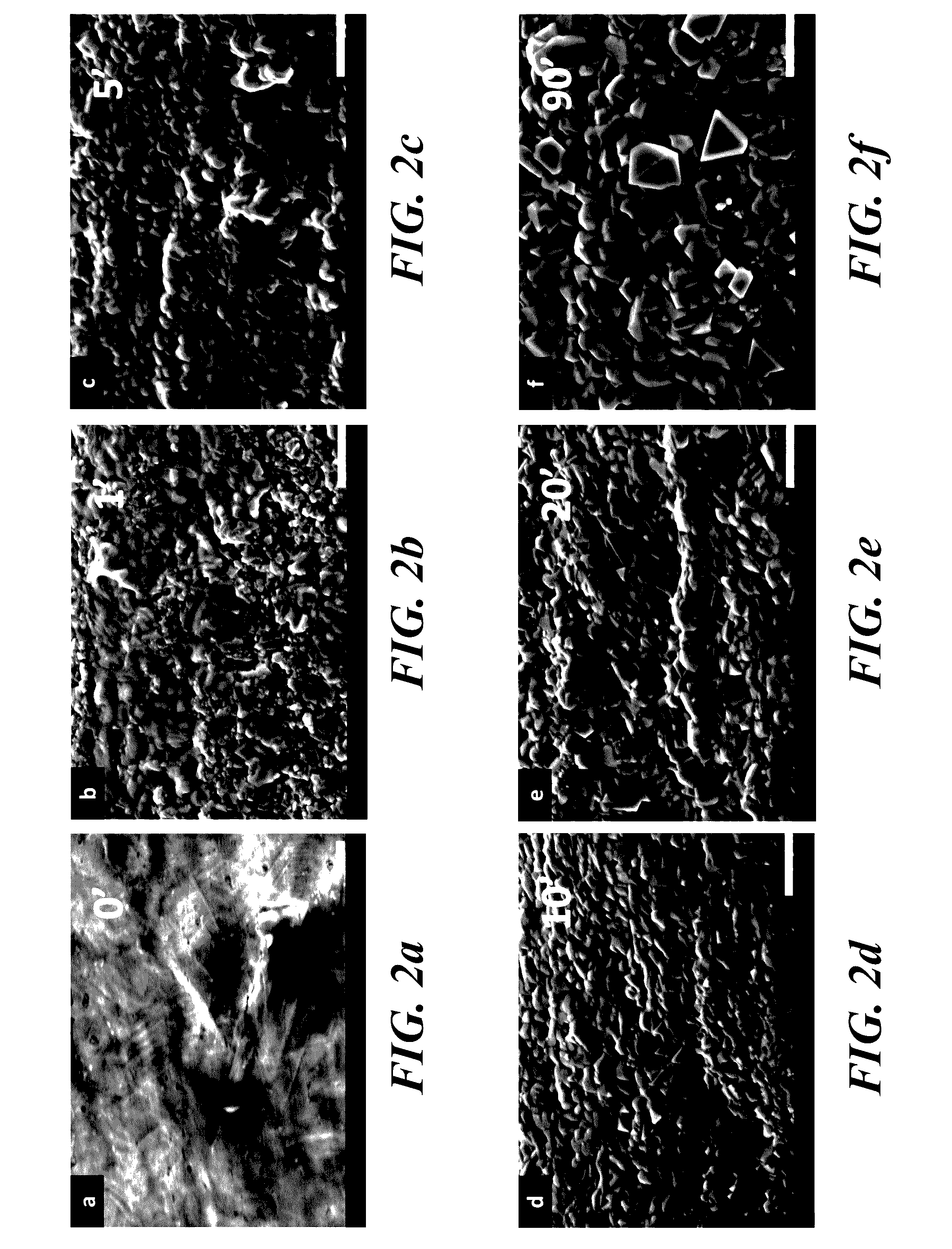
[0043]Scanning electron microscopy (SEM) was performed using a Hitachi S-4800 electron microscope equipped with energy dispersive spectroscopy (EDS). SEM was used to reveal the surface morphology and elemental composition of the substrates, as well as of the synthesized CNTs. An accelerating voltage of 3 kV, a beam current of 10 μA, and a working distance of 8.2 mm were applied for SEM imaging, whereas an accelerating voltage of 30 kV, a beam current of 10 μA and a working distance of 15 mm were applied for EDS analysis.

[0044]Atomic force microscopy (AFM) was conducted using an Agilent 5500 instrument to investigate the substrate surface roughness down to the nanometer scale. AFM scanning was performed on the SS samples after oxidative heat treatment for 1, 5, 10, or 20 minutes. An untreated steel sample was also investigated as a control. The samples were cut into 1 cm by 1 cm small pieces and were immobilized on glass cover sl...

example 2

Effect of Heat Treatment on Surface Reactivity

[0048]An Autolab PGSTAT 30 potentiostat (Metrohm USA, formerly Brinkman Instruments) was used for cyclic voltammetry measurements in a 3.56% (by weight) sodium chloride solution, made by dissolving 34 g of reagent grade NaCl in 920 mL of distilled water. After different oxidative heat treatments, SS samples with dimensions of 8 mm×6.25 mm were exposed to the NaCl solution. Voltammetry was carried out at room temperature in a three-electrode cell. All potentials were measured with respect to a Ag / AgCl reference electrode (212 mV vs. SHE), and anodic currents are shown as positive. All the measurements were collected after stable open circuit potentials (Eocp) of the electrodes in the solution were achieved.

[0049]Potentiodynamic measurements showed that the cyclic voltammograms of all the heat treated SS meshes had similar shapes (FIG. 4), but all were distinguishable from cyclic voltammograms of the untreated SS mesh. Specifically, a peak...

example 3

Synthesis of Carbon Nanotubes

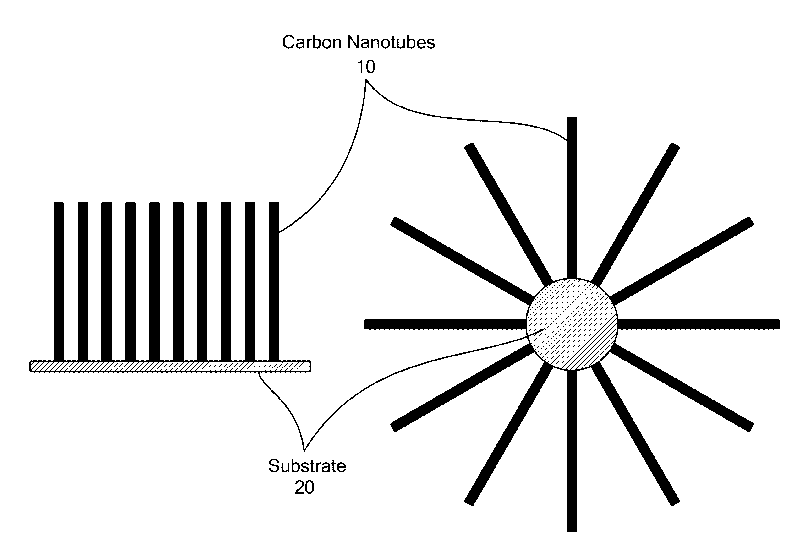
[0052]CNT synthesis experiments were conducted in a two-stage reactor (described in reference [8]), where feedstocks of solid post-consumer polymers (polyethylene, polystyrene, etc.) were pyrolytically gasified to supply gaseous hydrocarbons and hydrogen that are needed for the growth of the CNTs on pre-treated 316L SS mesh substrates / catalysts.

[0053]To achieve conversion of solid hydrocarbon fuels to CNTs, quantities of a solid feedstock, either polyethylene or polystyrene in pelletized form was first thermally pyrolyzed into a stream of gaseous decomposition products (pyrolyzates) inside a pyrolyzer furnace at 600˜800° C. Pyrolysis occurred in a nitrogen atmosphere with a flowrate of 1 standard liter per minute (slpm), which prevented the ignition and combustion of the pyrolyzates. The pyrolyzates then entered the second furnace where rolled up catalyst SS substrates were pre-inserted. Growth of CNTs occurred on the catalyst substrates at a furnace tem...


PUM

PropertyMeasurementUnit
temperatureaaaaaaaaaa
surface roughnessaaaaaaaaaa

Abstract

Methods for activating the surface of steel alloys to produce catalytic substrates for the synthesis of carbon nanomaterials by chemical vapor deposition are provided. Steel alloy substrates in a variety of forms are activated by brief (10 sec to 30 min) pre-treatment at high temperature (600-1000° C.) in an oxidizing environment (e.g., air) to activate the catalyst. Upon high temperature oxidative treatment, the initially smooth and protective chromium oxide coating layer of the steel alloy is destroyed, and the catalyst surface roughness progressively increases. Upon exposure of the pre-treated SS substrates to pyrolyzed hydrocarbon gases in nitrogen, carbon nanotubes are readily formed, and their diameters correlate with substrate surface roughness. Forests of vertically aligned nanotubes can be prepared with the method.

Description

CROSS REFERENCE TO RELATED APPLICATIONS[0001]This application claims the priority of U.S. Provisional Application No. 61 / 859,804 filed Jul. 30, 2013 and entitled “Expedient and Cost-Effective Preparation of Catalytic Substrates for Growing Carbon Nanomaterials”, the whole of which is hereby incorporated by reference.BACKGROUND[0002]Carbon nanotubes (CNTs) have been studied for more than two decades since their discovery [1-3]. With their increasing commercialization, it is important to integrate CNT processing with existing manufacturing methods [4,5]. Efforts have been made to reduce the major expenditures in CNT production, which are the carbonaceous feedstocks (raw materials), the catalyst, and power consumption. For instance, municipal and industrial waste plastics and process biomass residues have been proposed as low-cost feedstock alternatives, [6-13] and stainless steel (SS) screens or chips have been proposed as cost-effective, dual-purpose substrates and catalysts [14, 15]...

Claims


Application Information

Patent Timeline
Patent Type & Authority Applications(United States)
IPC IPC(8): B01J23/889C01B31/02B01J35/10B01J37/08B01J23/26B01J35/00
CPCB01J23/8892B01J23/26B01J35/0006B01J35/10B01J37/082Y10S977/843C01B2202/06C01B2202/08B82Y40/00B82Y30/00Y10S977/752C01B31/0233B01J37/0225B01J37/0226B01J23/8878C01B32/162
Inventor ZHUO, CHUANWEILEVENDIS, YIANNIS
Owner NORTHEASTERN UNIV
Why Eureka
Try Eureka