Lithium Anode-Protecting Polymer Layer for a Lithium Metal Secondary Battery and Manufacturing Method

a secondary battery and lithium metal technology, applied in the direction of cell components, final product manufacturing, sustainable manufacturing/processing, etc., can solve the problems of internal electrical shorting and thermal runaway, unsafe conditions in the battery, and further commercialization, and achieve the effect of improving the lithium ion conductivity of the polymer

Active Publication Date: 2018-10-18
GLOBAL GRAPHENE GRP INC
View PDF4 Cites 60 Cited by
  • Summary
  • Abstract
  • Description
  • Claims
  • Application Information

AI Technical Summary

Benefits of technology

[0024]In some embodiments, the high-elasticity polymer may form a mixture, blend, or semi-IPN with a lithium ion-conducting polymer selected from poly(ethylene oxide) (PEO), Polypropylene oxide (PPO), poly(acrylonitrile) (PAN), poly(methyl methacrylate) (PMMA), poly(vinylidene fluoride) (PVdF

Problems solved by technology

Unfortunately, upon cycling, the lithium metal resulted in the formation of dendrites that ultimately caused unsafe conditions in the battery.
Even now, cycling stability and safety concerns remain the primary factors preventing the further commercialization of Li metal batteries for EV, HEV, and microelectronic device applications.
These issues are primarily due to the high tendency for Li to form dendrite structures during repeated charge-discharge cycles or an overcharge, leading to internal electrical shorting and thermal runaway.
It is clear that such an anode structure, consisting of at least 3 or 4 layers, is too complex and too costly to make and use.
Despite these earlier efforts, no rechargeable Li metal batteries have yet succeeded in the market place.
This is likely due to the notion that these prior art approaches still have major deficiencies.
For instance, in several cases, the anode or electrolyte structures are too complex.
In others, the materials are too costly or the processes for making these materials are too laborious or difficult.
Solid electrolytes typically have a low lithium ion conductivity, are difficult to produce and di

Method used


Image

  • Lithium Anode-Protecting Polymer Layer for a Lithium Metal Secondary Battery and Manufacturing Method
  • Lithium Anode-Protecting Polymer Layer for a Lithium Metal Secondary Battery and Manufacturing Method
  • Lithium Anode-Protecting Polymer Layer for a Lithium Metal Secondary Battery and Manufacturing Method

Examples


example 3

Cells Containing Metal Fluoride Nano Particle-Based Cathode and a PETEA-Based High-Elasticity Polymer-Protected Lithium Anode

[0111]For serving as an anode lithium metal-protecting layer, pentaerythritol tetraacrylate (PETEA), Formula 3, was used as a monomer:

[0112]In a representative procedure, the precursor solution was composed of 1.5 wt. % PETEA (C17H20O8) monomer and 0.1 wt. % azodiisobutyronitrile (AIBN, C8H12N4) initiator dissolved in a solvent mixture of 1,2-dioxolane (DOL) / dimethoxymethane (DME)(1:1 by volume). The PETEA / AIBN precursor solution was cast onto a lithium metal layer pre-deposited on a Cu foil surface to form a precursor film, which was polymerized and cured at 70° C. for half an hour to obtain a lightly cross-linked polymer.

[0113]Additionally, the reacting mass, PETEA / AIBN (without conductive additive), was cast onto a glass surface to form several films that were polymerized and cured to obtain cross-linked polymers having different degrees of cross-linking. T...

example 4

c Cell Containing a Metal Naphthalocyanine / Reduced Graphene Oxide (FePc / RGO) Hybrid Particulate Cathode and a High Elasticity Polymer-Protected Li Foil Anode

[0117]Particles of combined FePc / graphene sheets were obtained by ball-milling a mixture of FePc and RGO in a milling chamber for 30 minutes. The resulting FePc / RGO mixture particles were potato-like in shape. Some of these mixture particles were encapsulated by an UHMW PAN polymer using the pan-coating procedure. Two lithium cells were prepared, each containing a Li foil anode, a porous separator, and a cathode layer of FePc / RGO particles (encapsulated or un-encapsulated).

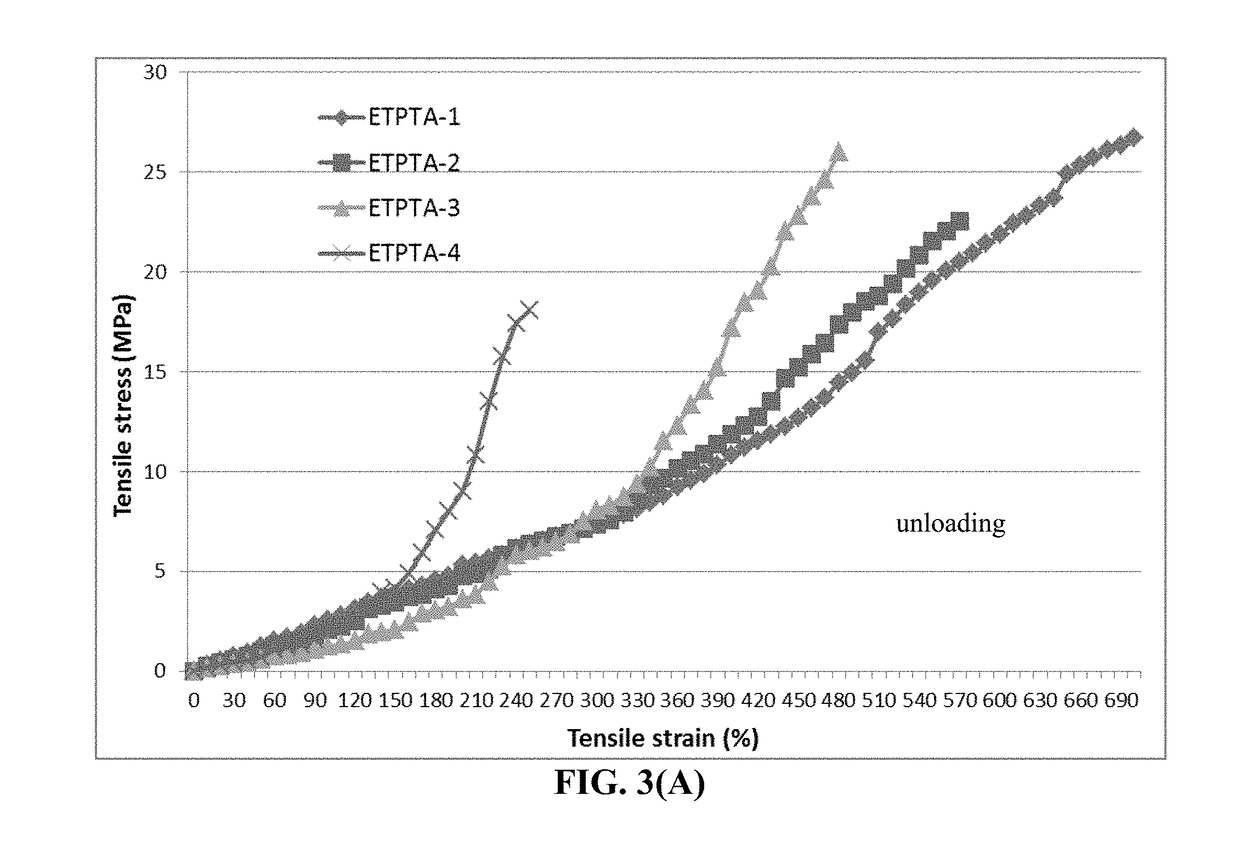
[0118]For preparation of an ETPTA semi-IPN polymer, the ETPTA (Mw=428 g / mol, trivalent acrylate monomer), EGMEA (Mw=482 g / mol, monovalent acrylate oligomer), and 2-hydroxy-2-methyl-1-phenyl-1-propanone (HMPP, a photoinitiator) were dissolved in a solvent (propylene carbonate, PC) to form a solution. The weight ratio between HMPP and the ETPTA / EGMEA mixture was...

example 5

s Containing an Anode-Protecting Layer and a Cathode Containing Sulfur-Impregnated Activated Carbon Particles

[0120]One way to combine sulfur with a conducting material (e.g. carbon / graphite particles) is to use a solution or melt mixing process. Highly porous activated carbon particles, chemically etched meso-carbon micro-balls (activated MCMBs), and exfoliated graphite worms were mixed with sulfur melt at 117-120° C. (slightly above the melting point of S, 115.2° C.) for 10-60 minutes to obtain sulfur-impregnated carbon particles.

[0121]FIG. 7 shows the cathode specific capacity values of two Li—S batteries having a cathode active material based on a S-impregnated activated MCMB: one cell having a cross-linked ETPTA-protected anode and the other one having no anode protection layer. It is clear that the lightly cross-linked ETPTA polymer layer implemented at the anode is highly beneficial to the cycle stability of the Li—S battery.


PUM


Abstract

Provided is lithium secondary battery comprising a cathode, an anode, and an electrolyte or separator-electrolyte assembly disposed between the cathode and the anode, wherein the anode comprises: (a) a foil or coating of lithium or lithium alloy; and (b) a thin layer of a high-elasticity polymer disposed between the foil/coating and the electrolyte (or separator-electrolyte assembly), having a recoverable tensile strain no less than 2%, a lithium ion conductivity no less than 10−6 S/cm at room temperature, and a thickness from 1 nm to 10 μm, wherein the high-elasticity polymer contains a cross-linked network of polymer chains having an ether linkage, nitrile-derived linkage, benzo peroxide-derived linkage, ethylene oxide linkage, propylene oxide linkage, vinyl alcohol linkage, cyano-resin linkage, triacrylate monomer-derived linkage, tetraacrylate monomer-derived linkage, or a combination thereof in the cross-linked network of polymer chains.

Description

FIELD OF THE INVENTION[0001]The present invention relates to the field of rechargeable lithium metal battery having a lithium metal layer (in a form of thin lithium foil, coating, or sheet) as an anode active material and a method of manufacturing same.BACKGROUND OF THE INVENTION[0002]Lithium-ion and lithium (Li) metal cells (including Lithium-sulfur cell, Li-air cell, etc.) are considered promising power sources for electric vehicle (EV), hybrid electric vehicle (HEV), and portable electronic devices, such as lap-top computers and mobile phones. Lithium metal has the highest capacity (3,861 mAh / g) compared to any other metal or metal-intercalated compound (except Li4.4Si) as an anode active material. Hence, in general, rechargeable Li metal batteries have a significantly higher energy density than lithium ion batteries.[0003]Historically, rechargeable lithium metal batteries were produced using non-lithiated compounds having high specific capacities, such as TiS2, MoS2, MnO2, CoO2 ...

Claims


Application Information

Patent Timeline
IPC IPC(8): H01M4/62H01M10/0525H01M4/48H01M12/08H01M4/38H01M4/40H01M4/525H01M4/58
CPCH01M4/5825H01M4/582H01M4/5815H01M4/628H01M4/525H01M4/483H01M12/08H01M4/382H01M4/405H01M10/0525H01M4/134H01M4/1395H01M10/052Y02E60/10Y02P70/50
Inventor PAN, BAOFEIHE, HUIZHAMU, ARUNAJANG, BOR Z.
Owner GLOBAL GRAPHENE GRP INC
Why Eureka
Try Eureka