Method and apparatus for producing atomic flows of molecular gases

a technology of molecular gas and atomic flow, which is applied in the field of methods and, can solve the problems of inability to obtain hot atoms from sources, less development of neutral chemically active particles, and limited effectiveness of atomic hydrogen sources

Inactive Publication Date: 2004-07-20
ATOMIC HYDROGEN TECH
View PDF14 Cites 11 Cited by
  • Summary
  • Abstract
  • Description
  • Claims
  • Application Information

AI Technical Summary

Problems solved by technology

However, the sources of neutral chemically active particles were less developed, as compared to the sources of plasma and charged particles.
Additionally, this source suffers from incapability of obtaining hot atoms, because of a low temperature of the heated metal surface (.about.2000 K).
However, the effectiveness of such an atomic hydrogen source is limited by a small cross-section of electron-stimulated desorption of atoms.
This leads to an increase of the pollution of a semiconductor structure under treatment by tungsten vapor and other products of the desorption process.
An RF discharge based source [18] has a high working pressure, thereby limiting its technological application and impeding the use thereof in super-high-vacuum systems and systems with a relatively low exhaust rate, and consequently, reducing the possibility of obtaining hot atoms (since a high number of interactions between the atoms and molecules in a gas phase results in the reduction of the average energy of atoms).
Additionally, this source is characterized by a high energy of ions in the plasma of RF discharge, which may lead to sputtering of the constructional elements of the source and contamination of the surface of a semiconductor structure under treatment, as well as radiation damage and charging of the structure during the ion bombardment thereof.
Nevertheless, microwave ECR discharge based sources have a complicated construction of both a discharge cell and its power supply source.
The need for a discharge cell that meets the specific requirements of geometry, and the need for a strong magnetic field in plasma impede the integration of these sources with standard vacuum equipment.
High voltage leads to the high probability of contamination of a semiconductor structure under treatment by the cathode ion sputtering products, as well as the increased probability of defects formation in near-surface layers of the structure (as a result of ion bombardment thereof).
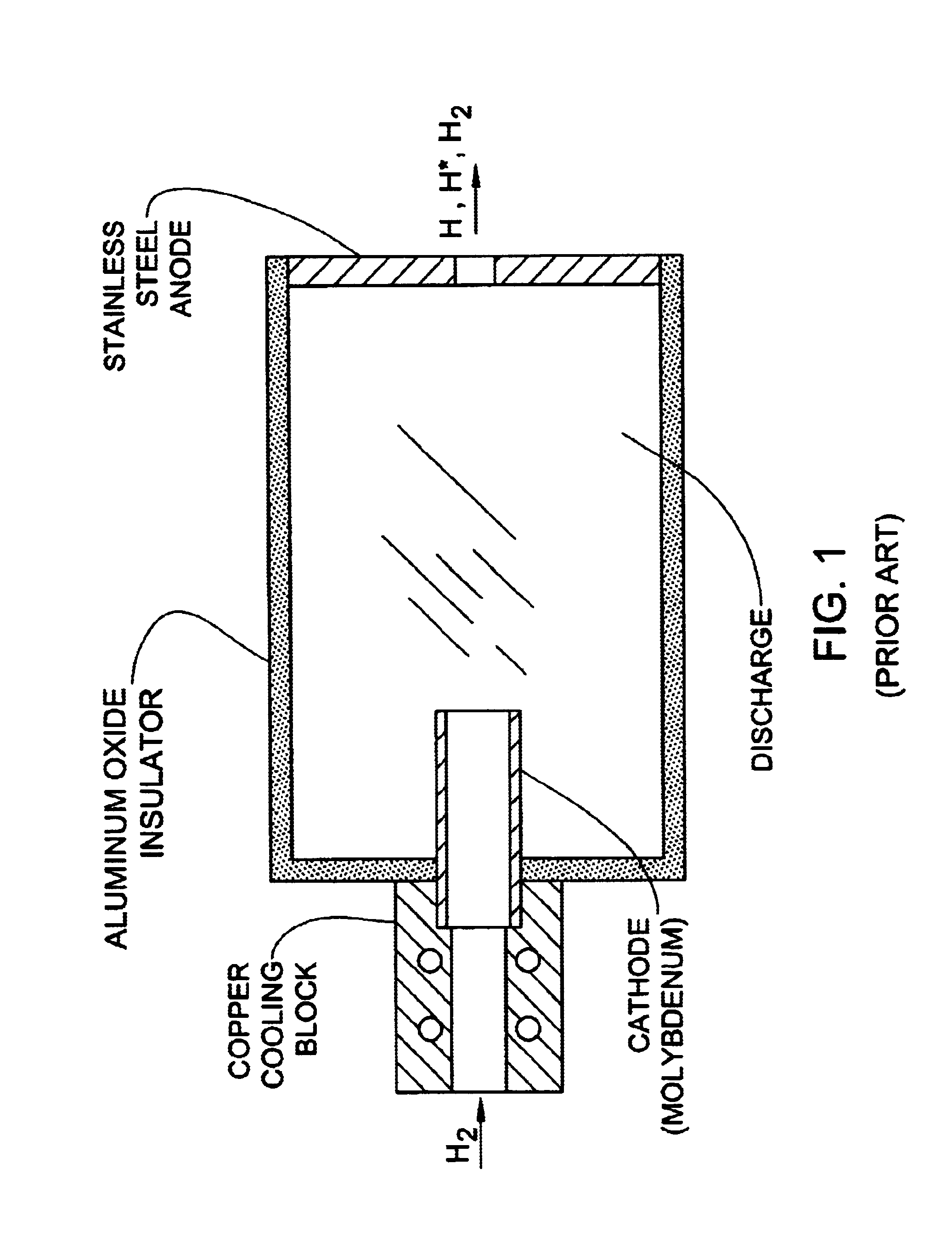
The electrodes' geometry used in the source of FIG. 1 provides for a short path of electrons in the volume of the discharge cell, which prevents the effective use of the entire electron energy on the processes of ionization of atoms (molecules) and the dissociation of molecules.
However, in the case of a glow discharge, this causes a growth of discharge voltage and formation of cathode spots, which increases the probability of contamination and damages of the surface of a semiconductor structure.
This source, however, suffers from too high a working pressure of hydrogen in the discharge cell, and too narrow range of working pressure values.
Incapability of this source for operating at reduced pressure values renders it impossible for use in super-high-vacuum systems and systems with low pumping rate.
This magnetron discharge causes heating and creation of thermionic emission from the hollow cathode, thereby causing intensive injection of thermionic electrons into plasma.
This source, however, does not provide a sufficiently high density of the output atomic hydrogen flow.
Additionally, it is characterized by a short operational time with the same electrodes.
The factor that the source quickly goes out of use is associated with the destroy of that part of the self-heating thin-wall hollow cathode which penetrates into the anode cavity.
The hollow cathode is destroyed by ion sputtering, as well as by quick breaking of the electrode material due its over-heating caused by insufficient heat conductance through the thin walls of the hollow cathode.
This, however, will require significant increase of the discharge current in order to keep the high density of discharge current and, consequently, a high degree of dissociation of molecules.
All these factors lead to a complicated construction of the discharge cell and increase in power supply.
One of the major problems of atomic hydrogen sources consists of contamination of the atomic hydrogen flow by impurities caused by erosion of electrode in discharge.

Method used


Image

  • Method and apparatus for producing atomic flows of molecular gases
  • Method and apparatus for producing atomic flows of molecular gases
  • Method and apparatus for producing atomic flows of molecular gases

Examples


example 2

The present example demonstrates the effect of increasing the atomic hydrogen output while utilizing transition from the source operation without a plasma jet to the operational mode with the plasma jet flowing through the emitting aperture into vacuum. An additional dissociation of hydrogen molecules occurring in the plasma jet, due to the oscillating electrons emitted from the butt-surface of the self-heating electrode and accelerated at the cathode potential drop, under a condition when the generated atoms are incapable of recombining on the cold walls of the cell, leads to a significant increase of the density of the atomic hydrogen flow.

The following table presents experimental data corresponding to the atomic hydrogen output for both operational modes, with and without the plasma jet. In these experiments the discharge cell of the above example of FIG. 5B, wherein the emitting aperture diameter is 0.5 mm, pressure in the vacuum chamber is 1.3.times.10.sup.-2 Pa. The atomic hyd...

example 3

The present example demonstrates the effect of decreasing the atomic hydrogen output by passing from the discharge cell operation mode with the second auxiliary discharge being a penning discharge (FIG. 5B) to its operational mode with the auxiliary discharge being a Penning discharge with hollow cathode. As can be seen from the experimental results presented in the table below, this change in the operational mode of the discharge cell results in the decrease of the atomic hydrogen output by a factor of 2.5.

example 4

The present example demonstrates how the source of the present invention can be used for cleaning the surface Al.sub.0.6 Ga.sub.0.4 As. The cleaning procedure was carried out in the flow of atomic hydrogen within a system of vacuum deposition of thin metal films. The discharge current of the atomic hydrogen source was equal to 2 A, and the voltage of discharge was 200V. The pressure of the residual atmosphere in a vacuum chamber was about (4-10).times.10.sup.-5 Pa. The pressure of hydrogen during the cleaning process was maintained at a level of 10.sup.-2 Pa, the temperature of the samples treatment T was changed from 300 to 400 C., and the treatment time t changed from 3 min to 90 min. Investigation of the surface cleaning used Auger electron-spectroscopy with layer-by-layer etching. To avoid the effects of oxidation of the samples' surfaces when they are transported into the chamber of Auger spectrometer, the samples were fed to the deposition zone immediately after being cleaned ...


PUM

PropertyMeasurementUnit
pressureaaaaaaaaaa
energyaaaaaaaaaa
diameteraaaaaaaaaa

Abstract

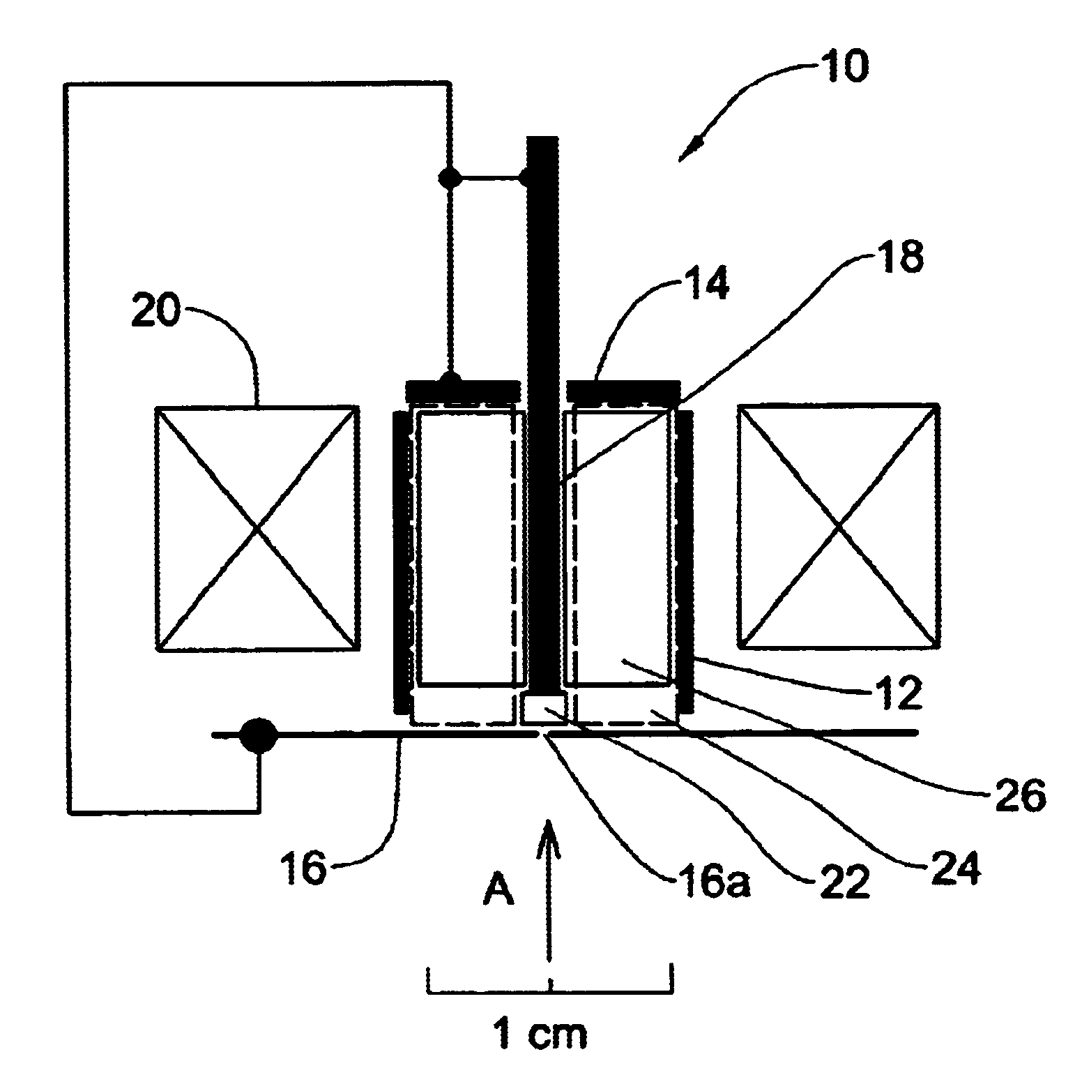
A method and device are presented for producing an intensive flow of atoms from an input flow of a molecular gas. Effects of ignition of a gas discharge of a complex type and dissociation of the gas molecules by electron impact in a discharge cell are utilized. The flow of atoms is output from the discharge cell through at least one emitting aperture. The complex gas discharge is composed of a main discharge and two auxiliary discharges of different types ignited in substantially coinciding zones of the discharge cell. The main discharge is an arc Penning discharge ignited in the vicinity of at least one emitting aperture. The first auxiliary discharge is a magnetron discharge with heated cathode, and the second auxiliary discharge is either a Penning discharge, or a Penning discharge with hollow cathode. The dissociation of the gas molecules is thereby carried out in the complex discharge and results in creation of the flow of hot and thermally atoms.

Description

This invention relates to a method and apparatus for producing flows of molecular gas atoms, in particular an atomic hydrogen flow. The invention is particularly useful in the manufacture, of semiconductor devices and integrated circuits.RELATED ARTThe following is a list of references, which is intended for a better understanding of the background of the present invention.1. Leone S., Jpn. J. Appl. Phys., 1995, 34. p. 2073-2082;2. Orlikovsky A. A., Microelectronics, 1999, 28(5), p. 344-362;3. Roussean A. et al., Pulsed microwave discharge: a very efficient H atom source, J. Phys. D: Appl. Phys., 1994, 27, p.2439-2441;4. Popov O. A., Waldron H., J. Vac. Sci. Technol. A., 1989, 7(3), p. 914-917;5. Kroon R., Jpn. J. Appl. Phys., 1997, 36, p. 5068-5071;6. Bardos L., Barankova H., Berg S., Appl. Phys. Lett., 1997, 70(5), p. 577-579;7. Lepert G., Thieme H. J., Osten H. J., J. Electrochem. Soc. 1995, V. 142. 1, p. 191-195;8. Sugaya T., Kawabe M., Jpn. J. Appl. Phys. 1991, 30(3A), p. L402-...

Claims


Application Information

Patent Timeline
Patent Type & Authority Patents(United States)
IPC IPC(8): H05H3/02H05H3/00
CPCH05H3/02
Inventor KAGADEI, VALERY A.PROSKUROVSKY, DMITRY I.
Owner ATOMIC HYDROGEN TECH
Why Eureka
Try Eureka